MomentInvariants Architecture#
Rotation-invariant Pattern Detection#
For pattern detection, the orientation of the pattern is usually not known a priory. The process should not be decelerated more than necessary while the pattern detection algorithm looks for all possible rotated copies of the template. Therefore, rotation invariance is a critical requirement. Moment invariants can achieve rotation invariance without the need for point to point correlations, which are difficult to generate in smooth fields. For an introduction, we recommend
Flusser, J., Suk, T., & Zitová, B. (2016). 2D and 3D Image Analysis by Moments. John Wiley & Sons.
We have implemented the prototypes of two vtk filters that together are able to perform pattern detection. The algorithm, which we used, is described in
Bujack, R., & Hagen, H. (2017). Moment Invariants for Multi-Dimensional Data. In Modeling, Analysis, and Visualization of Anisotropy (pp. 43-64). Springer, Cham.
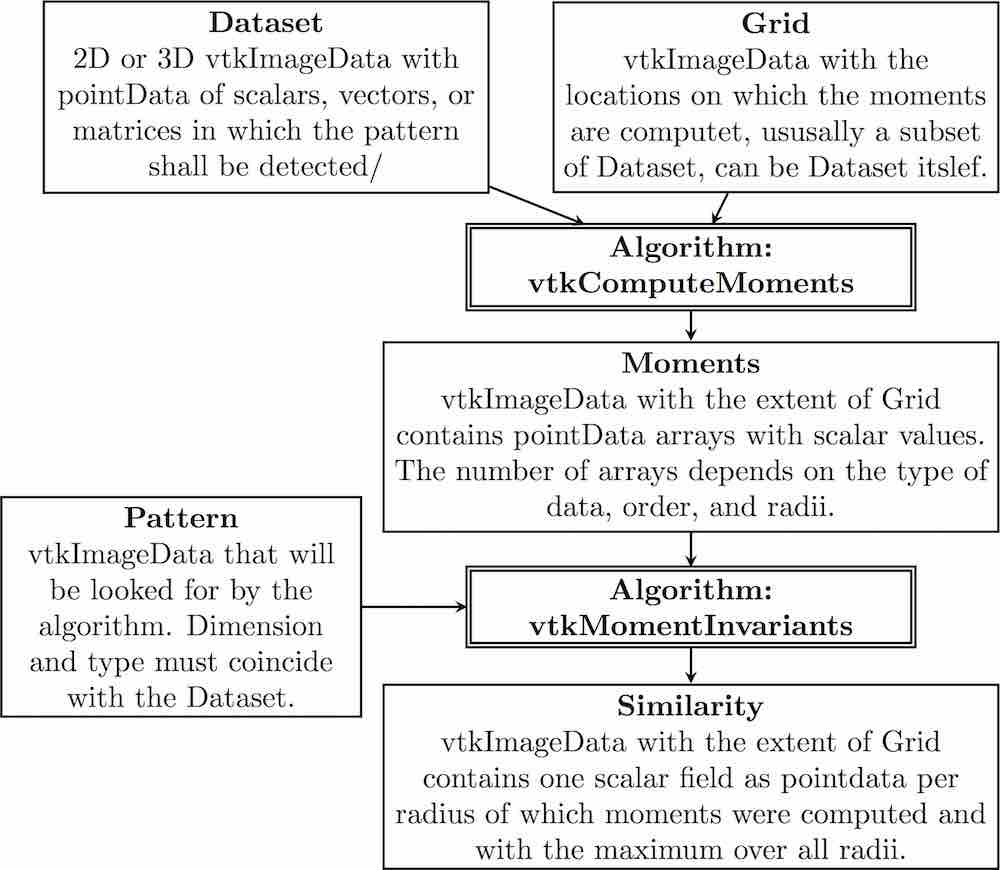
The first filter computes the moments and the second one performs the normalization based on the given pattern and computes the similarity. They are able to handle two- and three-dimensional scalar, vector, and matrix fields in the format of a vtkImageData. The architecture with inputs and outputs and their types can be found in the following figure.
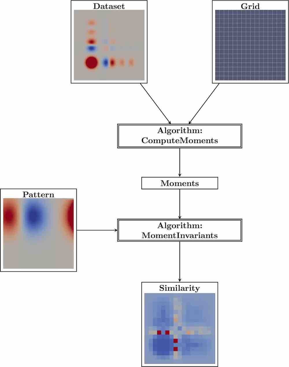
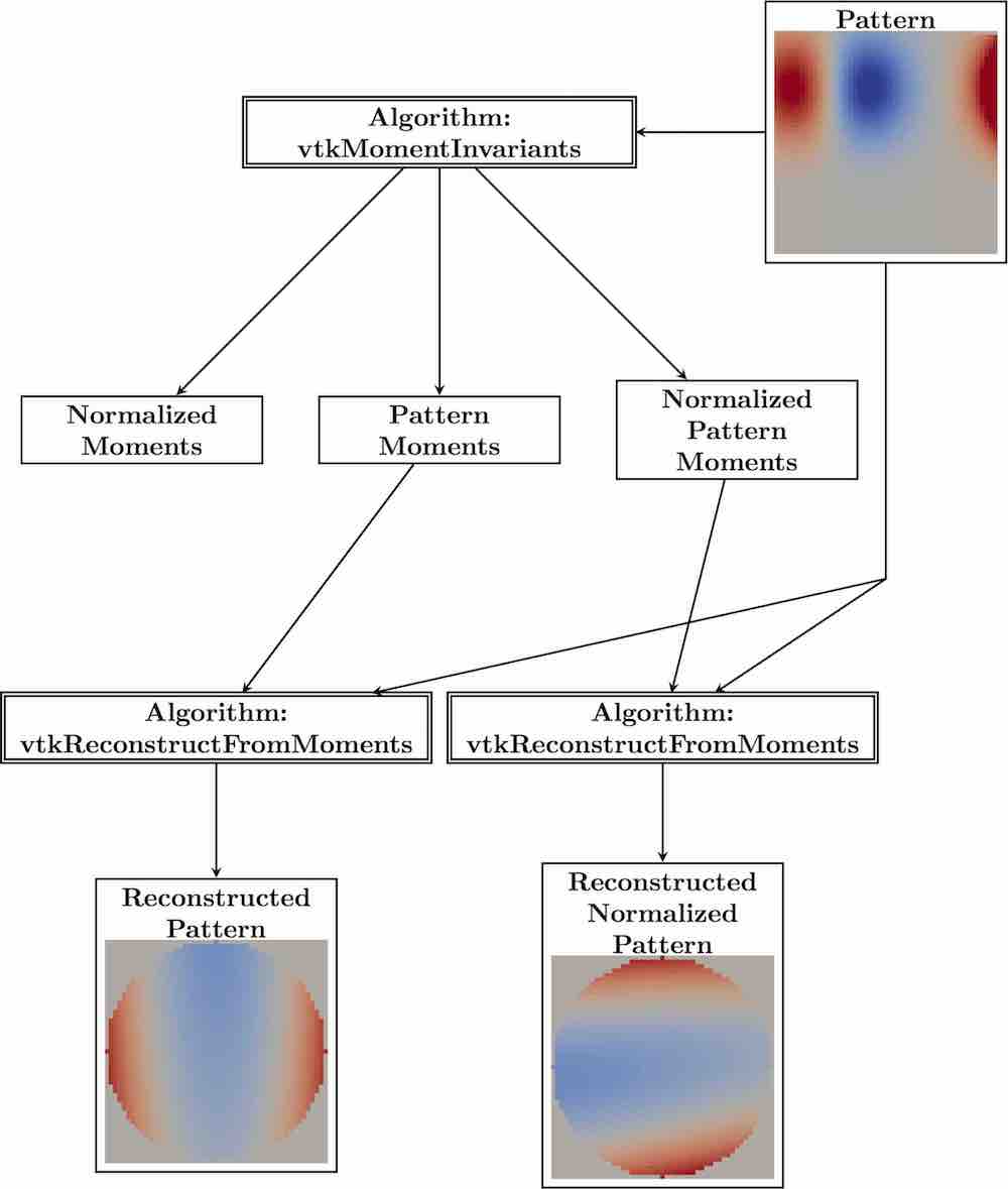
The architecture illustrated with example images is shown the following figure.
Extensions#
The MomentInvariants module contains actually a bunch of extra algorithms and helper classes.
The class vtkMomentsHelper provides functions for the moments computation that will be needed by vtkComputeMoments and vtkMomentInvariants.
The class vtkMomentsTensor provides the functionality to treat tensors of arbitrary dimension and rank. It supports addition, outer product, and contractions.
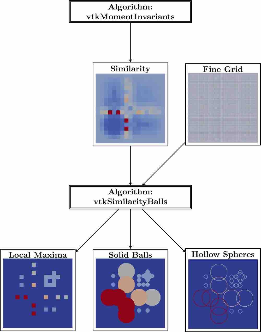
The algorithm vtkSimilarityBalls is a filter that takes the similarity field as produced by vtkMomentInvariants and a grid of type vtkImageData. It computes the local maxima in space plus scale and produces the output localMaxSimilarity that contains the similarity value together with the corresponding radius at the maxima. All other points are zero. For further visualization, it also produces two output fields that encode the radius through drawing a solid ball or a hollow sphere around those places. The second input, i.e. the grid, steers the resolution of the balls. It is helpful if its extent is a multiple of the first input’s. Then, the circles are centered nicely. The spheres/circles are good for 2D visualizations, because they can be laid over a visualization of the field. The balls are good for 3D volume rendering or steering of the seeding of visualization elements. The 2D visualization is described in
Bujack, R., Hotz, I., Scheuermann, G., & Hitzer, E. (2015). Moment invariants for 2D flow fields via normalization in detail. IEEE transactions on visualization and computer graphics, 21(8), 916-929
and the 3D counterpart in
Bujack, R., Kasten, J., Hotz, I., Scheuermann, G., & Hitzer, E. (2015, April). Moment invariants for 3D flow fields via normalization. In Visualization Symposium (PacificVis), 2015 IEEE Pacific (pp. 9-16). IEEE.
A schematic overview of the use of vtkSimilarityBalls with example images is given in the following Figure.
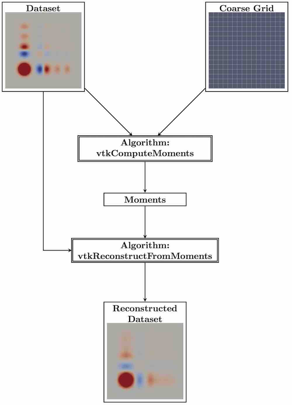
The algorithm vtkReconstructFromMoments is a filter that takes the momentData as produced by vtkComputeMoments or vtkMomentInvariants and a grid. It reconstructs the function from the moments, just like from the coefficients of a Taylor series. For the reconstruction, we need to orthonormalize the moments first. Then, we multiply the coefficients with their corresponding basis function and add them up. There are in principal three applications. First, if we put in the moments of the pattern and the grid of the pattern, we see which parts of the template the algorithm can actually grasp with the given order during the pattern detection. Tte following Figure shows images created using moments up to second order.
Second, if we put in the normalized moments of the pattern and the grid of the pattern, we can see how the standard position looks like. There might be several standard positions due to the ambiguity of the eigenvectors that differ by rotations of 180 degree and possibly a reflection. The algorithm will use the first one. In the previous Figure, the reflection along the x-axis would also be a standard position.
Third, if we put in the moments of the field and the original field data, we can see how well the subset of points, on which the moments were computed, actually represents the field. The following Figure depicts an example using a 16 x 16 coarse grid and moments up to second order.