VTK File Formats#
A lot of this material is taken from The VTK User’s Guide.
The Visualization Toolkit provides a number of source and writer objects to read and write popular data file formats. The Visualization Toolkit also provides some of its own file formats. The main reason for creating yet another data file format is to offer a consistent data representation scheme for a variety of dataset types, and to provide a simple method to communicate data between software. Whenever possible, we recommend that you use formats that are more widely used. But if this is not possible, the Visualization Toolkit formats described here can be used instead. Note that these formats may not be supported by many other tools.
There are three different styles of file formats available in VTK:
Legacy
It’s a serial formats that are easy to read and write either by hand or programmatically.
XML
More flexible but more complex than the legacy file format, it supports random access, parallel I/O, and portable data compression and are preferred to the serial VTK file formats whenever possible.
VTKHDF
This is a file format using the same concepts as the XML formats described above but relying on HDF5 for actual storage. It is simpler than the XML. It provides good I/O performance as well as robust and flexible parallel I/O capabilities and may to replace others file formats once it will be complete. It can be read/written using either hdf5 directly or the vtkhdf implementation in VTK.
Simple Legacy Formats#
The legacy VTK file formats consist of five basic parts.
The first part is the file version and identifier. This part contains the single line:
vtk DataFile Version x.x.This line must be exactly as shown with the exception of the version number x.x, which will vary with different releases of VTK. (Note: the current version number is 3.0. Version 1.0 and 2.0 files are compatible with version 3.0 files.)The second part is the header. The header consists of a character string terminated by end-of-line character \n. The header is 256 characters maximum. The header can be used to describe the data and include any other pertinent information.
The next part is the file format. The file format describes the type of file, either ASCII or binary. On this line the single word ASCII or BINARY must appear.
The fourth part is the dataset structure. The geometry part describes the geometry and topology of the dataset. This part begins with a line containing the keyword DATASET followed by a keyword describing the type of dataset.Then, depending upon the type of dataset, other keyword/data combinations define the actual data.
The final part describes the dataset attributes. This part begins with the keywords POINT_DATA or CELL_DATA, followed by an integer number specifying the number of points or cells, respectively. (It doesn’t matter whether POINT_DATA or CELL_DATA comes first.) Other keyword/data combinations then define the actual dataset attribute values (i.e., scalars, vectors, tensors, normals, texture coordinates, or field data).
An overview of the file format is shown in Figure 1:
| # vtk DataFile Version 2.0 | (1) |
| Really cool data | (2) |
| ASCII | BINARY | (3) |
| DATASET type ... | (4) |
| POINT_DATA type ... CELL_DATA type ... | (5) |
| Part 1: Header | Part 4: Geometry/Topology. Type is one of
STRUCTURED_POINTS STRUCTURED_GRID UNSTRUCTURED_GRID POLYDATA STRUCTURED_POINTS RECTILINEAR_GRID FIELD |
| Part 2:Title (256 characters
maximum, terminated with newline \n character) | Part 5: Dataset attributes. The number of data
items n of each type must match the number of points or cells in the dataset. (If type is FIELD, point and cell data should be omitted. |
| Part 3:Data type, either ASCII or BINARY |
Figure 1: Overview of five parts of VTK data file format.
The first three parts are mandatory, but the other two are optional. Thus you have the flexibility of mixing and matching dataset attributes and geometry, either by operating system file manipulation or using VTK filters to merge data. Keywords are case insensitive, and may be separated by whitespace. Before describing the data file formats please note the following.
dataType is one of the types bit, unsigned_char, char, unsigned_short, short, unsigned_int, int, unsigned_long, long, float, or double. These keywords are used to describe the form of the data, both for reading from file, as well as constructing the appropriate internal objects. Not all data types are supported for all classes.
All keyword phrases are written in ASCII form whether the file is binary or ASCII. The binary section of the file (if in binary form) is the data proper; i.e., the numbers that define points coordinates, scalars, cell indices, and so forth.
Indices are 0-offset. Thus the first point is point id 0.
If both the data attribute and geometry/topology part are present in the file, then the number of data values defined in the data attribute part must exactly match the number of points or cells defined in the geometry/topology part.
Cell types and indices are of type int.
Binary data must be placed into the file immediately after the “newline” (\n) character from the previous ASCII keyword and parameter sequence.
The geometry/topology description must occur prior to the data attribute description.
Binary Files#
Binary files in VTK are portable across different computer systems as long as you observe two conditions. First, make sure that the byte ordering of the data is correct, and second, make sure that the length of each data type is consistent.
Most of the time VTK manages the byte ordering of binary files for you. When you write a binary file on one computer and read it in from another computer, the bytes representing the data will be automatically swapped as necessary. For example, binary files written on a Sun are stored in big endian order, while those on a PC are stored in little endian order. As a result, files written on a Sun workstation require byte swapping when read on a PC. (See the class vtkByteSwap for implementation details.) The VTK data files described here are written in big endian form.
Some file formats, however, do not explicitly define a byte ordering form. You will find that data read or written by external programs, or the classes vtkVolume16Reader, vtkMCubesReader, and vtkMCubesWriter may have a different byte order depending on the system of origin. In such cases, VTK allows you to specify the byte order by using the methods
SetDataByteOrderToBigEndian()
SetDataByteOrderToLittleEndian()
Another problem with binary files is that systems may use a different number of bytes to represent an integer or other native type. For example, some 64-bit systems will represent an integer with 8-bytes, while others represent an integer with 4-bytes. Currently, the Visualization Toolkit cannot handle transporting binary files across systems with incompatible data length. In this case, use ASCII file formats instead.
Dataset Format#
The Visualization Toolkit supports five different dataset formats: structured points, structured grid, rectilinear grid, unstructured grid, and polygonal data. Data with implicit topology (structured data such as vtkImageData and vtkStructuredGrid) are ordered with x increasing fastest, then y, then z. These formats are as follows.
Structured Points. The file format supports 1D, 2D, and 3D structured point datasets. The dimensions nx, ny, nz must be greater than or equal to 1. The data spacing sx, sy, sz must be greater than 0. (Note: in the version 1.0 data file, spacing was referred to as “aspect ratio”. ASPECT_RATIO can still be used in version 2.0 data files, but is discouraged.)
DATASET STRUCTURED_POINTS
DIMENSIONS nx ny nz
ORIGIN x y z
SPACING sx sy yzStructured Grid. The file format supports 1D, 2D, and 3D structured grid datasets. The dimensions nx, ny, nz must be greater than or equal to 1. The point coordinates are defined by the data in the POINTS section. This consists of x-y-z data values for each point.
DATASET STRUCTURED_GRID
DIMENSIONS nx ny nz
POINTS n dataType
p0x p0y p0z
p1x p1y p1z
…
p(n-1)x p(n-1)y p(n-1)zRectilinear Grid. A rectilinear grid defines a dataset with regular topology, and semi-regular geometry aligned along the x-y-z coordinate axes. The geometry is defined by three lists of monotonically increasing coordinate values, one list for each of the x-y-z coordinate axes. The topology is defined by specifying the grid dimensions, which must be greater than or equal to 1.
DATASET RECTILINEAR_GRID
DIMENSIONS nx ny nz
X_COORDINATES nx dataType
x0 x1 … x(nx-1)
Y_COORDINATES ny dataType
y0 y1 … y(ny-1)
Z_COORDINATES nz dataType
z0 z1 … z(nz-1)Polygonal Data. The polygonal dataset consists of arbitrary combinations of surface graphics primitives vertices (and polyvertices), lines (and polylines), polygons (of various types), and triangle strips. Polygonal data is defined by the POINTS, VERTICES, LINES, POLYGONS, or TRIANGLE_STRIPS sections. The POINTS definition is the same as we saw for structured grid datasets. The VERTICES, LINES, POLYGONS, or TRIANGLE_STRIPS keywords define the polygonal dataset topology. Each of these keywords requires two parameters: the number of cells n and the size of the cell list size. The cell list size is the total number of integer values required to represent the list (i.e., sum of numPoints and connectivity indices over each cell). None of the keywords VERTICES, LINES, POLYGONS, or TRIANGLE_STRIPS is required.
DATASET POLYDATA
POINTS n dataType
p0x p0y p0z
p1x p1y p1z
…
p(n-1)x p(n-1)y p(n-1)z
VERTICES n size
numPoints0, i0, j0, k0, …
numPoints1, i1, j1, k1, …
…
numPointsn-1, in-1, jn-1, kn-1, …
LINES n size
numPoints0, i0, j0, k0, …
numPoints1, i1, j1, k1, …
…
numPointsn-1, in-1, jn-1, kn-1, …
POLYGONS n size
numPoints0, i0, j0, k0, …
numPoints1, i1, j1, k1, …
…
numPointsn-1, in-1, jn-1, kn-1, …
TRIANGLE_STRIPS n size
numPoints0, i0, j0, k0, …
numPoints1, i1, j1, k1, …
…
numPointsn-1, in-1, jn-1, kn-1, …Unstructured Grid. The unstructured grid dataset consists of arbitrary combinations of any possible cell type. Unstructured grids are defined by points, cells, and cell types. The CELLS keyword requires two parameters: the number of cells n and the size of the cell list size. The cell list size is the total number of integer values required to represent the list (i.e., sum of numPoints and connectivity indices over each cell). The CELL_TYPES keyword requires a single parameter: the number of cells n. This value should match the value specified by the CELLS keyword. The cell types data is a single integer value per cell that specified cell type (see vtkCell.h or Figure 2).
DATASET UNSTRUCTURED_GRID
POINTS n dataType
p0x p0y p0z
p1x p1y p1z
…
p(n-1)x p(n-1)y p(n-1)z
CELLS n size
numPoints0, i0, j0, k0, …
numPoints1, i1, j1, k1, …
numPoints2, i2, j2, k2, …
…
numPointsn-1, in-1, jn-1, kn-1, …
CELL_TYPES n
type0
type1
type2
…
typen-1Field. Field data is a general format without topological and geometric structure, and without a particular dimensionality. Typically field data is associated with the points or cells of a dataset. However, if the FIELD type is specified as the dataset type (see Figure1), then a general VTK data object is defined. Use the format described in the next section to define a field. Also see “Working With Field Data” on page 249 and the fourth example in this chapter Legacy File Examples.
Dataset Attribute Format#
The Visualization Toolkit supports the following dataset attributes: scalars (one to four components), vectors, normals, texture coordinates (1D, 2D, and 3D), tensors, and field data. In addition, a lookup table using the RGBA color specification, associated with the scalar data, can be defined as well. Dataset attributes are supported for both points and cells.
Each type of attribute data has a dataName associated with it. This is a character string (without embedded whitespace) used to identify a particular data. The dataName is used by the VTK readers to extract data. As a result, more than one attribute data of the same type can be included in a file. For example, two different scalar fields defined on the dataset points, pressure and temperature, can be contained in the same file. (If the appropriate dataName is not specified in the VTK reader, then the first data of that type is extracted from the file.)
Scalars. Scalar definition includes specification of a lookup table. The definition of a lookup table is optional. If not specified, the default VTK table will be used (and tableName should be “default”). Also note that the numComp variable is optional—by default the number of components is equal to one. (The parameter numComp must range between 1 and 4 inclusive; in versions of VTK prior to 2.3 this parameter was not supported.)
SCALARS dataName dataType numComp
LOOKUP_TABLE tableName
s0
s1
…
sn-1
The definition of color scalars (i.e., unsigned char values directly mapped to color) varies depending upon the number of values (nValues) per scalar. If the file format is ASCII, the color scalars are defined using nValues float values between (0,1). If the file format is BINARY, the stream of data consists of nValues unsigned char values per scalar value.
COLOR_SCALARS dataName nValues
c00 c01 … c0(nValues-1)
c10 c11 … c1(nValues-1)
…
c(n-1)0 c(n-1)1 … c(n-1)(nValues-1)Lookup Table. The tableName field is a character string (without embedded white space) used to identify the lookup table. This label is used by the VTK reader to extract a specific table. Each entry in the lookup table is a rgba[4] (red-green-blue-alpha) array (alpha is opacity where alpha=0 is transparent). If the file format is ASCII, the lookup table values must be float values between (0,1). If the file format is BINARY, the stream of data must be four unsigned char values per table entry.
LOOKUP_TABLE tableName size
r0 g0 b0 a0
r1 g1 b1 a1
…
rsize-1 gsize-1 bsize-1 asize-1Vectors.
VECTORS dataName dataType
v0x v0y v0z
v1x v1y v1z
…
v(n-1)x v(n-1)y v(n-1)zNormals. Normals are assumed normalized |n| = 1.
NORMALS dataName dataType
n0x n0y n0z
n1x n1y n1z
…
n(n-1)x n(n-1)y n(n-1)zTexture Coordinates. Texture coordinates of 1, 2, and 3 dimensions are supported.
TEXTURE_COORDINATES dataName dim dataType
t00 t01 … t0(dim-1)
t10 t11 … t1(dim-1)
…
t(n-1)0 t(n-1)1 … t(n-1)(dim-1)Tensors. Currently only real-valued, symmetric tensors are supported.
TENSORS dataName dataType
t000 t001 t002
t010 t011 t012
t020 t021 t022
t100 t101 t102
t110 t111 t112
t120 t121 t122
…
tn - 100 tn - 101 tn - 102
tn - 110 tn - 111 tn - 112
tn - 120 tn - 121 tn - 122Field Data. Field data is essentially an array of data arrays. Defining field data means giving a name to the field and specifying the number of arrays it contains. Then, for each array, the name of the array arrayName(i), the number of components of the array, numComponents, the number of tuples in the array, numTuples, and the data type, dataType, are defined.
FIELD dataName numArrays
arrayName0 numComponents numTuples dataType
f00 f01 … f0(numComponents-1)
f10 f11 … f1(numComponents-1)
…
f(numTuples-1)0 f(numTuples-1)1 … f(numTuples-1)(numComponents-1)
arrayName1 numComponents numTuples dataType
f00 f01 … f0(numComponents-1)
f10 f11 … f1(numComponents-1)
…
f(numTuples-1)0 f(numTuples-1)1 … f(numTuples-1)(numComponents-1)
…
arrayName(numArrays-1) numComponents numTuples dataType
f00 f01 … f0(numComponents-1)
f10 f11 … f1(numComponents-1)
…
f(numTuples-1)0 f(numTuples-1)1 … f(numTuples-1)(numComponents-1)
Legacy File Examples#
The first example is a cube represented by six polygonal faces. We define a single-component scalar, normals, and field data on the six faces. There are scalar data associated with the eight vertices. A lookup table of eight colors, associated with the point scalars, is also defined.
# vtk DataFile Version 2.0
Cube example
ASCII
DATASET POLYDATA
POINTS 8 float
0.0 0.0 0.0
1.0 0.0 0.0
1.0 1.0 0.0
0.0 1.0 0.0
0.0 0.0 1.0
1.0 0.0 1.0
1.0 1.0 1.0
0.0 1.0 1.0
POLYGONS 6 30
4 0 1 2 3
4 4 5 6 7
4 0 1 5 4
4 2 3 7 6
4 0 4 7 3
4 1 2 6 5
CELL_DATA 6
SCALARS cell_scalars int 1
LOOKUP_TABLE default
0
1
2
3
4
5
NORMALS cell_normals float
0 0 -1
0 0 1
0 -1 0
0 1 0
-1 0 0
1 0 0
FIELD FieldData 2
cellIds 1 6 int
0 1 2 3 4 5
faceAttributes 2 6 float
0.0 1.0 1.0 2.0 2.0 3.0 3.0 4.0 4.0 5.0 5.0 6.0
POINT_DATA 8
SCALARS sample_scalars float 1
LOOKUP_TABLE my_table
0.0
1.0
2.0
3.0
4.0
5.0
6.0
7.0
LOOKUP_TABLE my_table 8
0.0 0.0 0.0 1.0
1.0 0.0 0.0 1.0
0.0 1.0 0.0 1.0
1.0 1.0 0.0 1.0
0.0 0.0 1.0 1.0
1.0 0.0 1.0 1.0
0.0 1.0 1.0 1.0
1.0 1.0 1.0 1.0
The next example is a volume of dimension 3 by 4 by 6. Since no lookup table is defined, either the user must create one in VTK, or the default lookup table will be used.
# vtk DataFile Version 2.0
Volume example
ASCII
DATASET STRUCTURED_POINTS
DIMENSIONS 3 4 6
ASPECT_RATIO 1 1 1
ORIGIN 0 0 0
POINT_DATA 72
SCALARS volume_scalars char 1
LOOKUP_TABLE default
0 0 0 0 0 0 0 0 0 0 0 0
0 5 10 15 20 25 25 20 15 10 5 0
0 10 20 30 40 50 50 40 30 20 10 0
0 10 20 30 40 50 50 40 30 20 10 0
0 5 10 15 20 25 25 20 15 10 5 0
0 0 0 0 0 0 0 0 0 0 0 0
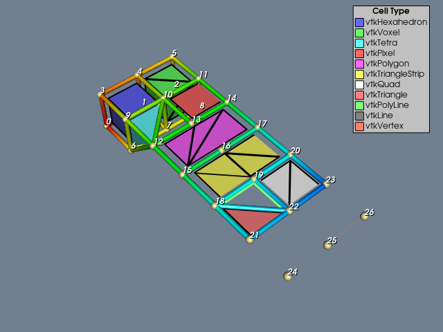
The third example is an unstructured grid containing twelve of the nineteen VTK cell types (see Figure 2 and Figure 3). Figure 2 shows all 16 of the linear cell types and was generated with the LinearCellDemo.
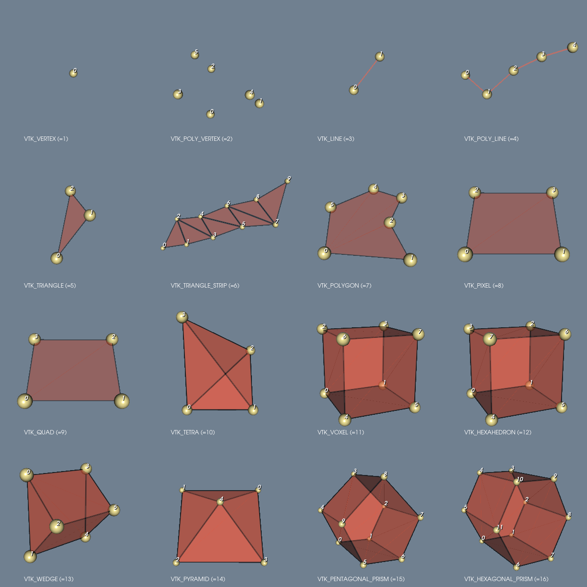
Figure 3 shows 16 of the non-linear cells and was generated with the IsoparametricCellsDemo.
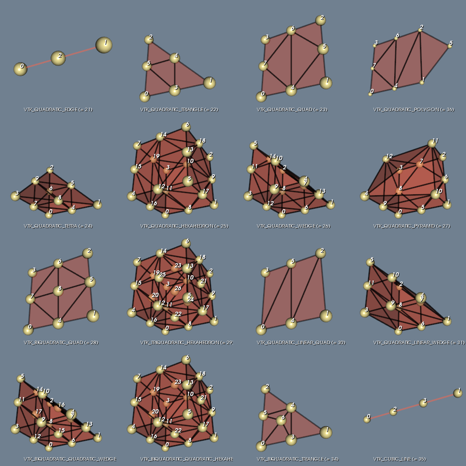
The file contains scalar and vector data. Figure 4 shows a presentation of this file generated by ReadLegacyUnstructuredGrid.
# vtk DataFile Version 2.0
Unstructured Grid Example
ASCII
DATASET UNSTRUCTURED_GRID

POINTS 27 float
0 0 0  1 0 0  2 0 0  0 1 0  1 1 0  2 1 0
0 0 1  1 0 1  2 0 1  0 1 1  1 1 1  2 1 1
0 1 2  1 1 2  2 1 2  0 1 3  1 1 3  2 1 3
0 1 4  1 1 4  2 1 4  0 1 5  1 1 5  2 1 5
0 1 6  1 1 6  2 1 6

CELLS 11 60
8 0 1 4 3 6 7 10 9
8 1 2 4 5 7 8 10 11
4 6 10 9 12
4 11 14 10 13
6 15 16 17 14 13 12
6 18 15 19 16 20 17
4 22 23 20 19
3 21 22 18
3 22 19 18
2 26 25
1 24

CELL_TYPES 11
12
11
10
8
7
6
9
5
4
3
1

POINT_DATA 27
SCALARS scalars float 1
LOOKUP_TABLE default
0.0 1.0 2.0 3.0 4.0 5.0
6.0 7.0 8.0 9.0 10.0 11.0
12.0 13.0 14.0 15.0 16.0 17.0
18.0 19.0 20.0 21.0 22.0 23.0
24.0 25.0 26.0

VECTORS vectors float
1 0 0  1 1 0  0 2 0  1 0 0  1 1 0  0 2 0
1 0 0  1 1 0  0 2 0  1 0 0  1 1 0  0 2 0
0 0 1  0 0 1  0 0 1  0 0 1  0 0 1  0 0 1
0 0 1  0 0 1  0 0 1  0 0 1  0 0 1  0 0 1
0 0 1  0 0 1  0 0 1

CELL_DATA 11
SCALARS scalars float 1
LOOKUP_TABLE CellColors
0.0 1.0 2.0 3.0 4.0 5.0
6.0 7.0 8.0 9.0 10.0

LOOKUP_TABLE CellColors 11
.4 .4 1 1
.4 1 .4 1
.4 1 1 1
1 .4 .4 1
1 .4 1 1
1 1 .4 1
1 1 1 1
1 .5 .5 1
.5 1 .5 1
.5 .5 .5 1
1 .5 .4 1
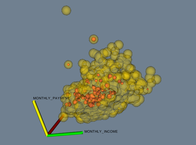
The fourth and final example is data represented as a field. You may also wish to see “Working With Field Data” on page 249 to see how to manipulate this data. The data file shown below can be found in its entirety here. The example FinanceFieldData generated Figure 5.
# vtk DataFile Version 2.0
Financial data in vtk field format
ASCII
FIELD financialData 6
TIME_LATE 1 3188 float
29.14 0.00 0.00 11.71 0.00 0.00 0.00 0.00
...(more stuff — 3188 total values)...
MONTHLY_PAYMENT 1 3188 float
7.26 5.27 8.01 16.84 8.21 15.75 10.62 15.47
...(more stuff)...
UNPAID_PRINCIPLE 1 3188 float
430.70 380.88 516.22 1351.23 629.66 1181.97 888.91 1437.83
...(more stuff)...
LOAN_AMOUNT 1 3188 float
441.50 391.00 530.00 1400.00 650.00 1224.00 920.00 1496.00
...(more stuff)...
INTEREST_RATE 1 3188 float
13.875 13.875 13.750 11.250 11.875 12.875 10.625 10.500
...(more stuff)...
MONTHLY_INCOME 1 3188 unsigned_short
39 51 51 38 35 49 45 56
...(more stuff)...
In this example, a field is represented using six arrays. Each array has a single component and 3,188 tuples. Five of the six arrays are of type float, while the last array is of type unsigned_short. Additional examples are available in the data directory.
XML File Formats#
VTK provides another set of data formats using XML syntax. While these formats are much more complicated than the original VTK format described previously (see Simple Legacy Formats), they support many more features. The major motivation for their development was to facilitate data streaming and parallel I/O. Some features of the format include support for compression, portable binary encoding, random access, big endian and little endian byte order, multiple file representation of piece data, and new file extensions for different VTK dataset types. XML provides many features as well, especially the ability to extend a file format with application specific tags.
There are two types of VTK XML data files: parallel and serial as described in the following.
Serial. File types designed for reading and writing by applications of only a single process. All of the data are contained within a single file.
Parallel. File types designed for reading and writing by applications with multiple processes executing in parallel. The dataset is broken into pieces. Each process is assigned a piece or set of pieces to read or write. An individual piece is stored in a corresponding serial file type. The parallel file type does not actually contain any data, but instead describes structural information and then references other serial files containing the data for each piece.
In the XML format, VTK datasets are classified into one of two categories.
Structured. The dataset is a topologically regular array of cells such as pixels and voxels (e.g., image data) or quadrilaterals and hexahedra (e.g., structured grid). Rectangular subsets of the data are described through extents. The structured dataset types are vtkImageData, vtkRectilinearGrid, and vtkStructuredGrid.
Unstructured. The dataset forms a topologically irregular set of points and cells. Subsets of the data are describedusing pieces. The unstructured dataset types are vtkPolyData and vtkUnstructuredGrid.
By convention, each data type and file type is paired with a particular file extension. The types and corresponding extensions are
ImageData (.vti) — Serial vtkImageData (structured).
PolyData (.vtp) — Serial vtkPolyData (unstructured).
RectilinearGrid (.vtr) — Serial vtkRectilinearGrid (structured).
StructuredGrid (.vts) — Serial vtkStructuredGrid (structured).
UnstructuredGrid (.vtu) — Serial vtkUnstructuredGrid (unstructured).
PImageData (.pvti) — Parallel vtkImageData (structured).
PPolyData (.pvtp) — Parallel vtkPolyData (unstructured).
PRectilinearGrid (.pvtr) — Parallel vtkRectilinearGrid (structured).
PStructuredGrid (.pvts) — Parallel vtkStructuredGrid (structured).
PUnstructuredGrid (.pvtu) — Parallel vtkUnstructuredGrid (unstructured).
All of the VTK XML file types are valid XML documents.
Note:
There is one case in which the file is not a valid XML document. When the AppendedData section is not encoded as base64, raw binary data is present that may violate the XML specification. This is not default behavior, and must be explicitly enabled by the user.
The document-level element is VTKFile:
<VTKFile type="ImageData" version="0.1" byte_order="LittleEndian">
...
</VTKFile>
The attributes of the element are:
type — The type of the file (the bulleted items in the previous list)..
version — File version number in “major.minor” format.
byte_order — Machine byte order in which data are stored. This is either “BigEndian” or “LittleEndian”.
compressor — Some data in the file may be compressed. This specifies the subclass of vtkDataCompressor that was used to compress the data.
Nested inside the VTKFile element is an element whose name corresponds to the type of the data format (i.e., the type attribute). This element describes the topology the dataset, and is different for the serial and parallel formats, which are described as follows.
Serial XML File Formats#
The VTKFile element contains one element whose name corresponds to the type of dataset the file describes. We refer to this as the dataset element, which is one of ImageData, RectilinearGrid, StructuredGrid, PolyData, or UnstructuredGrid. The dataset element contains one or more Piece elements, each describing a portion of the dataset. Together, the dataset element and Piece elements specify the entire dataset.
Each piece of a dataset must specify the geometry (points and cells) of that piece along with the data associated with each point or cell. Geometry is specified differently for each dataset type, but every piece of every dataset contains PointData and CellData elements specifying the data for each point and cell in the piece.
The general structure for each serial dataset format is as follows:
ImageData#
Each ImageData piece specifies its extent within the dataset’s whole extent. The points and cells are described implicitly by the extent, origin, and spacing. Note that the origin and spacing are constant across all pieces, so they are specified as attributes of the ImageData XML element as follows.
<VTKFile type="ImageData" ...>
  <ImageData WholeExtent="x1 x2 y1 y2 z1 z2"
   Origin="x0 y0 z0" Spacing="dx dy dz">
   <Piece Extent="x1 x2 y1 y2 z1 z2">
      <PointData>...</PointData>
      <CellData>...</CellData>
   </Piece>
   </ImageData>
</VTKFile>
RectilinearGrid#
Each RectilinearGrid piece specifies its extent within the dataset’s whole extent. The points are described by the Coordinates element. The cells are described implicitly by the extent.
<VTKFile type="RectilinearGrid" ...>
  <RectilinearGrid WholeExtent="x1 x2 y1 y2 z1 z2">
    <Piece Extent="x1 x2 y1 y2 z1 z2">
    <PointData>...</PointData>
    <CellData>...</CellData>
    <Coordinates>...</Coordinates>
    </Piece>
  </RectilinearGrid>
</VTKFile>
StructuredGrid#
Each StructuredGrid piece specifies its extent within the dataset’s whole extent. The points are described explicitly by the Points element. The cells are described implicitly by the extent.
<VTKFile type="StructuredGrid" ...>
  <StructuredGrid WholeExtent="x1 x2 y1 y2 z1 z2">
    <Piece Extent="x1 x2 y1 y2 z1 z2">
    <PointData>...</PointData>
    <CellData>...</CellData>
    <Points>...</Points>
    </Piece>
  </StructuredGrid>
</VTKFile>
PolyData#
Each PolyData piece specifies a set of points and cells independently from the other pieces. The points are described explicitly by the Points element. The cells are described explicitly by the Verts, Lines, Strips, and Polys elements.
<VTKFile type="PolyData" ...>
  <PolyData>
    <Piece NumberOfPoints="#" NumberOfVerts="#" NumberOfLines="#"
      NumberOfStrips="#" NumberOfPolys="#">
    <PointData>...</PointData>
    <CellData>...</CellData>
    <Points>...</Points>
    <Verts>...</Verts>
    <Lines>...</Lines>
    <Strips>...</Strips>
    <Polys>...</Polys>
   </Piece>
  </PolyData>
</VTKFile>
UnstructuredGrid#
Each UnstructuredGrid piece specifies a set of points and cells independently from the other pieces. The points are described explicitly by the Points element. The cells are described explicitly by the Cells element.
<VTKFile type="UnstructuredGrid" ...>
  <UnstructuredGrid>
    <Piece NumberOfPoints="#" NumberOfCells="#">
    <PointData>...</PointData>
    <CellData>...</CellData>
    <Points>...</Points>
    <Cells>...</Cells>
    </Piece>
  </UnstructuredGrid>
</VTKFile>
Every dataset describes the data associated with its points and cells with PointData and CellData XML elements as follows:
  <PointData Scalars="Temperature" Vectors="Velocity">
    <DataArray Name="Velocity" .../>
    <DataArray Name="Temperature" .../>
    <DataArray Name="Pressure" .../>
  </PointData>
VTK allows an arbitrary number of data arrays to be associated with the points and cells of a dataset. Each data array is described by a DataArray element which, among other things, gives each array a name. The following attributes of PointData and CellData are used to specify the active arrays by name:
Scalars — The name of the active scalars array, if any.
Vectors — The name of the active vectors array, if any.
Normals — The name of the active normals array, if any.
Tensors — The name of the active tensors array, if any.
TCoords — The name of the active texture coordinates array, if any.
Some datasets describe their points and cells using different combinations of the following common elements:
Points — The Points element explicitly defines coordinates for each point individually. It contains one DataArray element describing an array with three components per value, each specifying the coordinates of one point.
    <Points>
      <DataArray NumberOfComponents="3" .../>
    </Points>
Coordinates — The Coordinates element defines point coordinates for an extent by specifying the ordinate along each axis for each integer value in the extent’s range. It contains three DataArray elements describing the ordinates along the x-y-z axes, respectively.
    <Coordinates>
      <DataArray .../>
      <DataArray .../>
      <DataArray .../>
    </Coordinates>
Verts, Lines, Strips, and Polys — The Verts, Lines, Strips, and Polys elements define cells explicitly by specifying point connectivity. Cell types are implicitly known by the type of element in which they are specified. Each element contains two DataArray elements. The first array specifies the point connectivity. All the cells’ point lists are concatenated together. The second array specifies the offset into the connectivity array for the end of each cell.
    <Verts>
      <DataArray type="Int32" Name="connectivity" .../>
      <DataArray type="Int32" Name="offsets" .../>
    </Verts>
Cells — The Cells element defines cells explicitly by specifying point connectivity and cell types. It contains three DataArray elements. The first array specifies the point connectivity. All the cells’ point lists are concatenated together. The second array specifies the offset into the connectivity array for the end of each cell. The third array specifies the type of each cell. (Note: the cell types are defined in Figure 2 and Figure 3.)
    <Cells>
      <DataArray type="Int32" Name="connectivity" .../>
      <DataArray type="Int32" Name="offsets" .../>
      <DataArray type="UInt8" Name="types" .../>
    </Cells>
All of the data and geometry specifications use DataArray elements to describe their actual content as follows:
DataArray — The DataArray element stores a sequence of values of one type. There may be one or more components per value.
    <DataArray type="Float32" Name="vectors" NumberOfComponents="3"
               format="appended" offset="0"/>
    <DataArray type="Float32" Name="scalars" format="binary">
               bAAAAAAAAAAAAIA/AAAAQAAAQEAAAIBA... </DataArray>
    <DataArray type="Int32" Name="offsets" format="ascii">
               10 20 30 ... </DataArray>
The attributes of the DataArray elements are described as follows: type — The data type of a single component of the array. This is one of Int8, UInt8, Int16, UInt16, Int32, UInt32, Int64, UInt64, Float32, Float64. Note: the 64-bit integer types are only supported if VTK_USE_64BIT_IDS is on (a CMake variable—see “CMake” on page 10) or the platform is 64-bit.
Name — The name of the array. This is usually a brief description of the data stored in the array.
NumberOfComponents — The number of components per value in the array.
format — The means by which the data values themselves are stored in the file. This is “ascii”, “binary”, or “appended”.
offset — If the format attribute is “appended”, this specifies the offset from the beginning of the appended data section to the beginning of this array’s data.
The format attribute chooses among the three ways in which data values can be stored:
format=”ascii” — The data are listed in ASCII directly inside the DataArray element. Whitespace is used for separation.
format=”binary” — The data are encoded in base64 and listed contiguously inside the DataArray element. Data may also be compressed before encoding in base64. The byte-order of the data matches that specified by the byte_order attribute of the VTKFile element.
format=”appended” — The data are stored in the appended data section. Since many DataArray elements may store their data in this section, the offset attribute is used to specify where each DataArray’s data begins. This format is the default used by VTK’s writers.
The appended data section is stored in an AppendedData element that is nested inside VTKFile after the dataset element:
  <VTKFile ...>
    ...
    <AppendedData encoding="base64">
                  _QMwEAAAAAAAAA...
    </AppendedData>
  </VTKFile>
The appended data section begins with the first character after the underscore inside the AppendedData element. The underscore is not part of the data, but is always present. Data in this section is always in binary form, but can be compressed and/or base64 encoded. The byte-order of the data matches that specified by the byte_order attribute of the VTKFile element. Each DataArray’s data are stored contiguously and appended immediately after the previous DataArray’s data without a separator. The DataArray’s offset attribute indicates the file position offset from the first character after the underscore to the beginning its data.
Parallel File Formats#
The parallel file formats do not actually store any data in the file. Instead, the data are broken into pieces, each of which is stored in a serial file of the same dataset type.
The VTKFile element contains one element whose name corresponds to the type of dataset the file describes, but with a “P” prefix. We refer to this as the parallel dataset element, which is one of PImageData, PRectilinearGrid, PStructuredGrid, PPolyData, or PUnstructuredGrid.
The parallel dataset element and those nested inside specify the types of the data arrays used to store points, pointn data, and cell data (the type of arrays used to store cells is fixed by VTK). The element does not actually contain any data, but instead includes a list of Piece elements that specify the source from which to read each piece. Individual pieces are stored in the corresponding serial file format. The parallel file needs to specify the type and structural information so that readers can update pipeline information without actually reading the pieces’ files.
The general structure for each parallel dataset format is as follows:
PImageData#
The PImageData element specifies the whole extent of the dataset and the number of ghost-levels by which the extents in the individual pieces overlap. The Origin and Spacing attributes implicitly specify the point locations. Each Piece element describes the extent of one piece and the file in which it is stored.
  <VTKFile type="PImageData" ...>
    <PImageData WholeExtent="x1 x2 y1 y2 z1 z2"
                GhostLevel="#" Origin="x0 y0 z0" Spacing="dx dy dz">
      <PPointData>...</PPointData>
      <PCellData>...</PCellData>
      <Piece Extent="x1 x2 y1 y2 z1 z2" Source="imageData0.vti"/>
      ...
   </PImageData>
  </VTKFile>
PRectilinearGrid#
The PRectilinearGrid element specifies the whole extent of the dataset and the number of ghost-levels by which the extents in the individual pieces overlap. The PCoordinates element describes the type of arrays used to specify the point ordinates along each axis, but does not actually contain the data. Each Piece element describes the extent of one piece and the file in which it is stored.
  <VTKFile type="PRectilinearGrid" ...>
    <PRectilinearGrid WholeExtent="x1 x2 y1 y2 z1 z2"
                      GhostLevel="#">
      <PPointData>...</PPointData>
      <PCellData>...</PCellData>
      <PCoordinates>...</PCoordinates>
      <Piece Extent="x1 x2 y1 y2 z1 z2"
             Source="rectilinearGrid0.vtr"/>
      ...
    </PRectilinearGrid>
  </VTKFile>
PStructuredGrid#
The PStructuredGrid element specifies the whole extent of the dataset and the number of ghost-levels by which the extents in the individual pieces overlap. The PPoints element describes the type of array used to specify the point locations, but does not actually contain the data. Each Piece element describes the extent of one piece and the file in which it is stored.
  <VTKFile type="PStructuredGrid" ...>
    <PStructuredGrid WholeExtent="x1 x2 y1 y2 z1 z2"
                     GhostLevel="#">
      <PPointData>...</PPointData>
      <PCellData>...</PCellData>
      <PPoints>...</PPoints>
      <Piece Extent="x1 x2 y1 y2 z1 z2"
             Source="structuredGrid0.vts"/>
      ...
    </PStructuredGrid>
  </VTKFile>
PPolyData#
The PPolyData element specifies the number of ghost-levels by which the individual pieces overlap. The PPoints element describes the type of array used to specify the point locations, but does not actually contain the data. Each Piece element specifies the file in which the piece is stored.
  <VTKFile type="PPolyData" ...>
    <PPolyData GhostLevel="#">
      <PPointData>...</PPointData>
      <PCellData>...</PCellData>
      <PPoints>...</PPoints>
      <Piece Source="polyData0.vtp"/>
      ...
    </PPolyData>
  </VTKFile>
PUnstructuredGrid#
The PUnstructuredGrid element specifies the number of ghost-levels by which the individual pieces overlap. The PPoints element describes the type of array used to specify the point locations, but does not actually contain the data. Each Piece element specifies the file in which the piece is stored.
  <VTKFile type="PUnstructuredGrid" ...>
    <PUnstructuredGrid GhostLevel="0">
      <PPointData>...</PPointData>
      <PCellData>...</PCellData>
      <PPoints>...</PPoints>
      <Piece Source="unstructuredGrid0.vtu"/>
      ...
    </PUnstructuredGrid>
  </VTKFile>
Every dataset uses PPointData and PCellData elements to describe the types of data arrays associated with its points and cells.
PPointData and PCellData — These elements simply mirror the PointData and CellData elements from the serial file formats. They contain PDataArray elements describing the data arrays, but without any actual data.
    <PPointData Scalars="Temperature" Vectors="Velocity">
      <PDataArray Name="Velocity" .../>
      <PDataArray Name="Temperature" .../>
      <PDataArray Name="Pressure" .../>
   </PPointData>
For datasets that need specification of points, the following elements mirror their counterparts from the serial file format:
PPoints — The PPoints element contains one PDataArray element describing an array with three components. The data array does not actually contain any data.
    <PPoints>
      <PDataArray NumberOfComponents="3" .../>
    </PPoints>
PCoordinates — The PCoordinates element contains three PDataArray elements describing the arrays used to specify ordinates along each axis. The data arrays do not actually contain any data.
    <PCoordinates>
      <PDataArray .../>
      <PDataArray .../>
      <PDataArray .../>
   </PCoordinates>
All of the data and geometry specifications use PDataArray elements to describe the data array types:
PDataArray — The PDataArray element specifies the type, Name, and optionally the NumberOfComponents attributes from the DataArray element. It does not contain the actual data. This can be used by readers to create the data array in their output without needing to read any real data, which is necessary for efficient pipeline updates in some cases.
<PDataArray type="Float32" Name="vectors" NumberOfComponents="3"/>
XML File Example#
The following is a complete example specifying a vtkPolyData representing a cube with some scalar data on its points and faces. 1
  <?xml version="1.0"?>
  <VTKFile type="PPolyData" version="0.1" byte_order="LittleEndian">
    <PPolyData GhostLevel="0">
      <PPointData Scalars="my_scalars">
        <PDataArray type="Float32" Name="my_scalars"/>
      </PPointData>
        <PCellData Scalars="cell_scalars" Normals="cell_normals">
          <PDataArray type="Int32" Name="cell_scalars"/>
           <PDataArray type="Float32" Name="cell_normals" NumberOfComponents="3"/>
        </PCellData>
        <PPoints>
          <PDataArray type="Float32" NumberOfComponents="3"/>
        </PPoints>
        <Piece Source="polyEx0.vtp"/>
    </PPolyData>
  </VTKFile>


  <?xml version="1.0"?>
    <VTKFile type="PolyData" version="0.1" byte_order="LittleEndian">
      <PolyData>
        <Piece NumberOfPoints="8" NumberOfVerts="0" NumberOfLines="0"
               NumberOfStrips="0" NumberOfPolys="6">
        <Points>
          <DataArray type="Float32" NumberOfComponents="3" format="ascii">
            0 0 0 1 0 0 1 1 0 0 1 0 0 0 1 1 0 1 1 1 1 0 1 1
          </DataArray>
        </Points>
        <PointData Scalars="my_scalars">
          <DataArray type="Float32" Name="my_scalars" format="ascii">
            0 1 2 3 4 5 6 7
         </DataArray>
        </PointData>
        <CellData Scalars="cell_scalars" Normals="cell_normals">
          <DataArray type="Int32" Name="cell_scalars" format="ascii">
           0 1 2 3 4 5
          </DataArray>
          <DataArray type="Float32" Name="cell_normals"
                     NumberOfComponents="3" format="ascii">
            0 0 -1 0 0 1 0 -1 0 0 1 0 -1 0 0 1 0 0
          </DataArray>
        </CellData>
        <Polys>
          <DataArray type="Int32" Name="connectivity" format="ascii">
             0 1 2 3 4 5 6 7 0 1 5 4 2 3 7 6 0 4 7 3 1 2 6 5
          </DataArray>
          <DataArray type="Int32" Name="offsets" format="ascii">
             4 8 12 16 20 24
          </DataArray>
        </Polys>
      </Piece>
    </PolyData>
   </VTKFile>
VTKHDF File Format#
The VTKHDF file format is a file format relying on HDF5.
It is meant to provide good I/O performance as well as robust and flexible parallel I/O capabilities.
It currently supports: PolyData, UnstructuredGrid, ImageData, OverlappingAMR, MultiBlockDataSet and the PartitionedDataSetCollection.
The current file format version is the 2.2.
Note: This development is iterative and the format is expected to grow in its support for more and more use cases.
Changelog#
VTKHDF - 2.2#
add support for temporal
OverlappingAMRadd official support for ignored data outside of
VTKHDF
VTKHDF - 2.1#
add specification in the format for
PartitionedDataSetCollectionandMultiBlockDataSet
VTKHDF - 2.0#
extends the specification for
PolyData.add support for
Temporaldataset forPolyData,ImageDataandUnstructuredGrid.
VTKHDF - 1.0#
add specification for these vtk data types:
UnstructuredGridImageDataOverlapping AMR
Extension#
The VTKHDF format generally uses the .vtkhdf extension. The .hdf
extension is also supported but is not preferred. There are no specific
extensions to differentiate between different types of dataset, serial
vs. distributed data or static vs. temporal data.
General Specification#
VTK HDF files start with a group called VTKHDF with two attributes:
Version, an array of two integers and Type, a string showing the
VTK dataset type stored in the file. Additional attributes can follow
depending on the dataset type. Currently, Version
is the array [2, 2] and Type can be ImageData, PolyData,
UnstructuredGrid, OverlappingAMR, PartitionedDataSetCollection or
MultiBlockDataSet.
Top-level groups outside of /VTKHDF do not contain any information related to VTK data model and are outside of the scope of this specification. They can be useful to store meta-information that could be read and written by custom VTKHDF implementations.
The data type for each HDF dataset is part of the dataset and it is
determined at write time. The reader matches the type of the dataset
with a H5T_NATIVE_ type and creates the VTK array of that
type. Consequently, the type at writing might be different than the
type at reading even on the same machine because for instance long
can be the same type as long long or int can be the same as long
on certain platforms. Also, vtkIdType is read as the C++ type it
represents (long or long long). Endianness conversions are done
automatically.
In the diagrams that follow, showing the HDF file structure for VTK datasets, the rounded blue rectangles are HDF groups and the gray rectangles are HDF datasets. Each rectangle shows the name of the group or dataset in bold font and the attributes underneath with regular font.
Image data#
The format for image data is detailed in the Figure 6 where the Type
attribute of the VTKHDF group is ImageData. An
ImageData (regular grid) is not split into partitions for parallel
processing. We rely on the writer to chunk the data to optimize
reading for a certain number of MPI ranks. Attribute data is stored in
a PointData or CellData array using hyper slabs. WholeExtent,
Origin, Spacing and Direction attributes have the same meaning
as the corresponding attributes for the vtkImageData dataset. Scalars,
Vectors, … string attributes for the PointData and CellData
groups specify the active attributes in the dataset.

Unstructured grid#
The format for unstructured grid is shown in Figure 7. In this case
the Type attribute of the VTKHDF group is UnstructuredGrid.
The unstructured grid is split into partitions, with a partition for
each MPI rank. This is reflected in the HDF5 file structure. Each HDF
dataset is obtained by concatenating the data for each partition. The
offset O(i) where we store the data for partition i is computed using:
O(i) = S(0) + … + S(i-1), i > 1 with O(0) = 0.
where S(i) is the size of partition i.
We describe the split into partitions using HDF5 datasets
NumberOfConnectivityIds, NumberOfPoints and NumberOfCells. Let n
be the number of partitions which usually correspond to the number of
the MPI ranks. NumberOfConnectivityIds has size n where
NumberOfConnectivityIds[i] represents the size of the Connectivity
array for partition i. NumberOfPoints and NumberOfCells are arrays
of size n, where NumberOfPoints[i] and NumberOfCells[i] are the number
of points and number of cells for partition i. The Points array
contains the points of the VTK dataset. Offsets is an array of size
∑ (S(i) + 1), where S(i) is the number of cells in partition i, indicating the index in
the Connectivity array where each cell’s points start.
Connectivity stores the lists of point ids for each cell, and
Types contain the cell information stored as described in
vtkCellArray documentation. Data for each partition is appended in a
HDF dataset for Points, Connectivity, Offsets, Types,
PointData and CellData. We can compute the size of partition i
using the following formulas:
Size of partition i |
|
|---|---|
Points |
NumberOfPoints[i] * 3 * sizeof(Points[0][0]) |
Connectivity |
NumberOfConnectivityIds[i] * sizeof(Connectivity[0]) |
Offsets |
(NumberOfCells[i] + 1) * sizeof(Offsets[0]) |
Types |
NumberOfCells[i] * sizeof(Types[i]) |
PointData |
NumberOfPoints[i] * sizeof(point_array_k[0]) |
CellData |
NumberOfCells[i] * sizeof(cell_array_k[0]) |

To read the data for its rank a node reads the information about all partitions, compute the correct offset and then read data from that offset.
Poly data#
The format for unstructured grid is shown in Figure 8. In this case
the Type attribute of the VTKHDF group is PolyData.
The poly data is split into partitions, with a partition for
each MPI rank. This is reflected in the HDF5 file structure. Each HDF
dataset is obtained by concatenating the data for each partition. The
offset O(i) where we store the data for partition i is computed using:
O(i) = S(0) + … + S(i-1), i > 1 with O(0) = 0.
where S(i) is the size of partition i. This is very similar to and
completely inspired by the UnstructuredGrid format.
The split into partitions of the point coordinates is exactly the same
as in the UnstructuredGrid format above. However, the split into
partitions of each of the category of cells (Vertices, Lines,
Polygons and Strips) using HDF5 datasets NumberOfConnectivityIds
and NumberOfCells. Let n be the number of partitions which usually
correspond to the number of the MPI ranks. {CellCategory}/NumberOfConnectivityIds has
size n where NumberOfConnectivityIds[i] represents the size of the {CellCategory}/Connectivity
array for partition i. NumberOfPoints and {CellCategory}/NumberOfCells are arrays
of size n, where NumberOfPoints[i] and {CellCategory}/NumberOfCells[i] are the number
of points and number of cells for partition i. The Points array
contains the points of the VTK dataset. {CellCategory}/Offsets is an array of size
∑ (S(i) + 1), where S(i) is the number of cells in partition i, indicating the index in
the {CellCategory}/Connectivity array where each cell’s points start.
{CellCategory}/Connectivity stores the lists of point ids for each cell.
Data for each partition is appended in a HDF dataset for Points, Connectivity, Offsets,
PointData and CellData. We can compute the size of partition i
using the following formulas:
Size of partition i |
|
|---|---|
Points |
NumberOfPoints[i] * 3 * sizeof(Points[0][0]) |
{CellCategory}/Connectivity |
{CellCategory}/NumberOfConnectivityIds[i] * sizeof({CellCategory}/Connectivity[0]) |
{CellCategory}/Offsets |
({CellCategory}/NumberOfCells[i] + 1) * sizeof({CellCategory}/Offsets[0]) |
PointData |
NumberOfPoints[i] * sizeof(point_array_k[0]) |
CellData |
(∑j {CellCategory_j}/NumberOfCells[i]) * sizeof(cell_array_k[0]) |
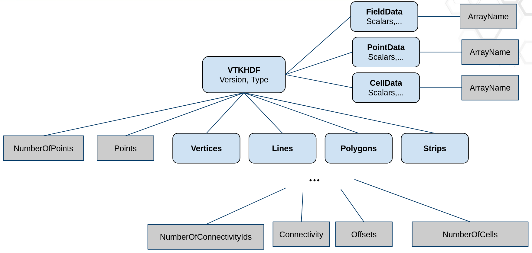
Figure 8. - Poly Data VTKHDF File Format#
To read the data for its rank a node reads the information about all partitions, compute the correct offset and then read data from that offset.
Overlapping AMR#
The format for Overlapping AMR is shown in Figure 9. In this case
the Type attribute of the VTKHDF group is OverlappingAMR.
The mandatory Origin parameter is a double triplet that defines
the global origin of the AMR data set.
Each level in an overlapping AMR file format (and data structure)
consists of a list of uniform grids with the same spacing from the
Spacing attribute. The Spacing attribute is a list a three doubles
describing the spacing in each x/y/z direction.
The AMRBox dataset contains the bounding box
for each of these grids. Each line in this dataset is expected to contain
6 integers describing the the indexed bounds in i, j, k space
(imin/imax/jmin/jmax/kmin/kmax).
The points and cell arrays for these grids are
stored serialized in one dimension and stored in a dataset in the
PointData or CellData group.

PartitionedDataSetCollection and MultiBlockDataSet#
The general VTKHDF format for vtkPartitionedDataSetCollection (PDC) and vtkMultiBlockDataSet (MB) is shown in Figure 10.
Both VTK data types share a common structure, with a few notable differences.
The Type attribute of the VTKHDF group for them should be PartitionedDataSetCollection or MultiBlockDataSet.
The most important element in this design is the Assembly group, direct child of the VTKHDF group.
This group describes the composite data hierarchy. The elements of the Assembly group do not contain the data directly.
Instead, the data blocks are stored as direct children of the VTKHDF group, without any hierarchy,
and any node in the Assembly group can use an HDF5 symbolic link
to the top-level datasets.
Here lies the main distinction between the PDC and MB formats.
For PDC, a group in the assembly that is not a softlink represents a node in the vtkAssembly associated to it, and
a softlink represents a dataset index associated to its parent node (similar to what the function AddDataSetIndex does in vtkDataAssembly).
This way, a single dataset can be used multiple times in the assembly without any additional storage cost.
Top-level datasets need to set an Index attribute to specify their index in the PDC flat structure.
On the other hand, MB structures work a little differently. First, they don’t need no index for their datasets, and
secondly, an assembly node that is not a softlink represents a nested vtkMultiBlockDataSet.
A softlink in the assembly represents a dataset nested in its parent vtkMultiBlockDataSet.
Again, this MB format can save space when a block is referenced multiple times.
Some additional detail about the format:
The data blocks should not be composite themselves : they can only be simple or partitioned types, but not using an assembly.
The Assembly group and its children need to track creation order to be able to keep subtrees ordered. For this, you need to set H5G properties
H5P_CRT_ORDER_TRACKEDandH5P_CRT_ORDER_INDEXEDon each group when writing the Assembly.For PDC, the assembly structure only needs to be traversed once at the beginning of the reading procedure (and can potentially be read and broadcasted only by the main process in a distributed context) to optimize file meta-data reading.
The block wise reading implementation and composite level implementation can be managed independently from each other.
It would be doable for each block to have its own time range and time steps in a temporal context with the full composite data set able to collect and expose a combined range and set of time values, but for now we only allow reading datasets that have all the same number of timesteps.
Reading performance can scale linearly with the number of blocks even in a distributed context.
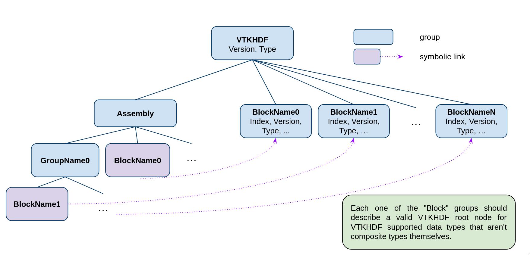
Figure 10. - PartitionedDataSetCollection/MultiBlockDataset VTKHDF File Format#
Temporal Data#
The generic format for all VTKHDF temporal data is shown in Figure 11.
The general idea is to take the static formats described above and use them
as a base to append all the time dependent data. As such, a file holding static
data has a very similar structure to a file holding dynamic data. An additional
Steps subgroup is added to the VTKHDF main group holding offset information
for each of the time steps as well as the time values. The choice to include offset
information as HDF5 datasets was made to reduce the quantity of meta-data in the
file to improve performance. This Steps group has one integer like attribute
NSteps indicating the number of steps in the temporal dataset.
The Steps group is structured as follows:
Values[dim = (NSteps)]: each entry indicates the time value for the associated time step.PartOffsets[dims = (NSteps)]: each entry indicates at which part offset to start reading the associated time step (relevant forUnstructured Grids andPoly Data).NumberOfParts[dims = (NSteps)]: each entry indicates how many parts the associated time step has (relevant forUnstructured Grids andPoly Data). This information is optional if there is a constant number of parts per time steps and the length ofVTKHDF/NumberOfPointsis equal toNumberOfPartsPerTimeStep x NSteps.PointOffsets[dims = (NSteps)]: each entry indicates where in theVTKHDF/Pointsdata set to start reading point coordinates for the associated time step (relevant forUnstructured GridandPoly Data).CellOffsets[dims = (NSteps, NTopologies)]: each entry indicates by how many cells to offset reading into the connectivity offset structures for the associated time step (relevant forUnstructured GridandPoly Data).Unstructured Grids only have one set of connectivity data and NTopologies = 1.Poly Data, however, haveVertices,Lines,PolygonsandStripsin that order and therefore NTopologies = 4.
ConnectivityIdOffsets[dims = (NSteps, NTopologies)]: each entry indicates by how many values to offset reading into the connectivity indexing structures for the associated time step (relevant forUnstructured GridandPoly Data).Unstructured Grids only have one set of connectivity data and NTopologies = 1.Poly Data, however, haveVertices,Lines,PolygonsandStripsin that order and therefore NTopologies = 4.
{Point,Cell,Field}DataOffsets/{ArrayName}[dims = (NSteps)]: each entry indicates by how many values to offset reading into the given array for the associated time step. In the absence of a data set, the appropriate geometry offsetting for the time step is used in its place.FieldDataSizes/{ArrayName}[dims = (NSteps, 2)]: each entry indicates the field data component and tuple size. In the absence of a data set, the maximum number of components and one tuple per step are considered.
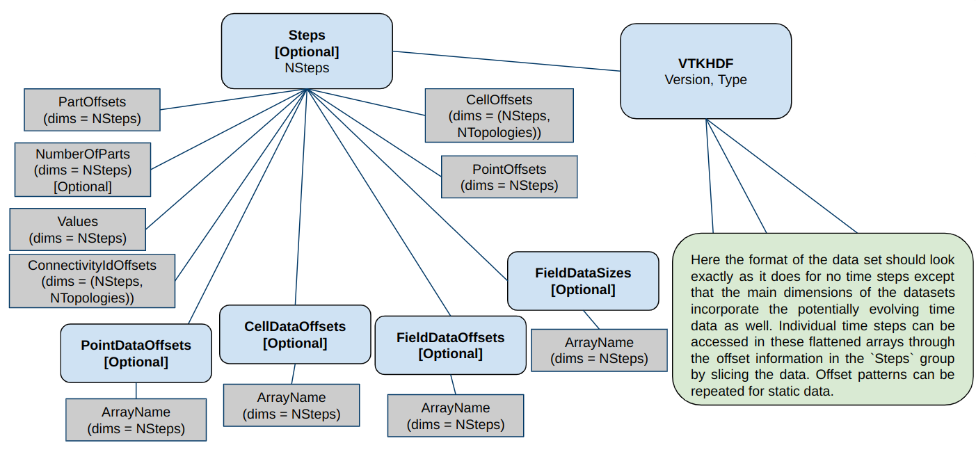
Figure 11. - Temporal Data VTKHDF File Format#
Writing incrementally to VTKHDF temporal datasets is relatively straightforward using the
appending functionality of HDF5 chunked data sets
(Chunking in HDF5).
Particularity regarding ImageData#
A particularity of temporal Image Data in the format is that the reader expects an additional
prepended dimension considering the time to be the first dimension in the multidimensional arrays.
As such, arrays described in temporal Image Data should have dimensions ordered as
(time, z, y, x).
Particularity regarding OverlappingAMR#
Currently only AMRBox and Point/Cell/Field data can be temporal, not the Spacing. Due to the
structure of the OverlappingAMR format, the format specify an intermediary group between the Steps
group and the Point/Cell/FieldDataOffset group named LevelX for each level where X is the
number of level. These Level groups will also contain 2 other datasets to retrieve the AMRBox:
AMRBoxOffsets: each entry indicates by how many AMR box to offset reading into theAMRBox.NumberOfAMRBox: the number of boxes contained in theAMRBoxfor each timestep.
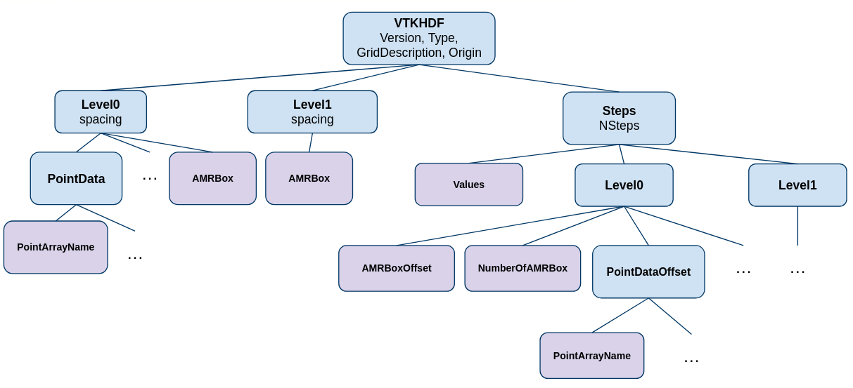
Figure 12. - Temporal OverlappingAMR VTKHDF File Format#
Limitations#
This specification and the reader available in VTK currently only supports ImageData, UnstructuredGrid, PolyData, Overlapping AMR, MultiBlockDataSet and Partitioned DataSet Collection. Other dataset types may be added later depending on interest and funding.
Examples#
We present three examples of VTK HDF files, shown using h5dump -A one
image file, one unstructured grid and one overlapping AMR.
These files can be examined in the VTK source code, by building VTK
and enabling testing (VTK_BUILD_TESTING). The two files are in the build directory
ExternalData at Testing/Data/mandelbrot-vti.hdf for the ImageData
and at Testing/Data/can-pvtu.hdf for the partitioned UnstructuredGrid
and Testing/Data/amr_gaussian_pulse.hdf for the overlapping AMR.
ImageData#
The image data file is a wavelet source produced in ParaView. Note that we don’t partition image data, so the same format is used for serial and parallel processing.
HDF5 "ExternalData/Testing/Data/mandelbrot-vti.hdf" {
GROUP "/" {
   GROUP "VTKHDF" {
      ATTRIBUTE "Direction" {
         DATATYPE  H5T_IEEE_F64LE
         DATASPACE  SIMPLE { ( 9 ) / ( 9 ) }
         DATA {
         (0): 1, 0, 0, 0, 1, 0, 0, 0, 1
         }
      }
      ATTRIBUTE "Origin" {
         DATATYPE  H5T_IEEE_F64LE
         DATASPACE  SIMPLE { ( 3 ) / ( 3 ) }
         DATA {
         (0): -1.75, -1.25, 0
         }
      }
      ATTRIBUTE "Spacing" {
         DATATYPE  H5T_IEEE_F64LE
         DATASPACE  SIMPLE { ( 3 ) / ( 3 ) }
         DATA {
         (0): 0.131579, 0.125, 0.0952381
         }
      }
      ATTRIBUTE "Type" {
         DATATYPE  H5T_STRING {
            STRSIZE 9;
            STRPAD H5T_STR_NULLPAD;
            CSET H5T_CSET_ASCII;
            CTYPE H5T_C_S1;
         }
         DATASPACE  SCALAR
         DATA {
         (0): "ImageData"
         }
      }
      ATTRIBUTE "Version" {
         DATATYPE  H5T_STD_I64LE
         DATASPACE  SIMPLE { ( 2 ) / ( 2 ) }
         DATA {
         (0): 1, 0
         }
      }
      ATTRIBUTE "WholeExtent" {
         DATATYPE  H5T_STD_I64LE
         DATASPACE  SIMPLE { ( 6 ) / ( 6 ) }
         DATA {
         (0): 0, 19, 0, 20, 0, 21
         }
      }
      GROUP "PointData" {
         ATTRIBUTE "Scalars" {
            DATATYPE  H5T_STRING {
               STRSIZE 18;
               STRPAD H5T_STR_NULLPAD;
               CSET H5T_CSET_ASCII;
               CTYPE H5T_C_S1;
            }
            DATASPACE  SCALAR
            DATA {
            (0): "IterationsGradient"
            }
         }
         DATASET "Iterations" {
            DATATYPE  H5T_IEEE_F32LE
            DATASPACE  SIMPLE { ( 22, 21, 20 ) / ( 22, 21, 20 ) }
         }
         DATASET "IterationsGradient" {
            DATATYPE  H5T_IEEE_F64LE
            DATASPACE  SIMPLE { ( 22, 21, 20, 3 ) / ( 22, 21, 20, 3 ) }
         }
         DATASET "Iterations_double" {
            DATATYPE  H5T_IEEE_F64LE
            DATASPACE  SIMPLE { ( 22, 21, 20 ) / ( 22, 21, 20 ) }
         }
         DATASET "point_index_llong" {
            DATATYPE  H5T_STD_I64LE
            DATASPACE  SIMPLE { ( 22, 21, 20 ) / ( 22, 21, 20 ) }
         }
         DATASET "xextent_int" {
            DATATYPE  H5T_STD_I32LE
            DATASPACE  SIMPLE { ( 22, 21, 20 ) / ( 22, 21, 20 ) }
         }
         DATASET "xextent_long" {
            DATATYPE  H5T_STD_I64LE
            DATASPACE  SIMPLE { ( 22, 21, 20 ) / ( 22, 21, 20 ) }
         }
         DATASET "xextent_uint" {
            DATATYPE  H5T_STD_U32LE
            DATASPACE  SIMPLE { ( 22, 21, 20 ) / ( 22, 21, 20 ) }
         }
         DATASET "xextent_ulong" {
            DATATYPE  H5T_STD_U64LE
            DATASPACE  SIMPLE { ( 22, 21, 20 ) / ( 22, 21, 20 ) }
         }
      }
   }
}
}
UnstructuredGrid#
The unstructured grid is the can example (only the can, not the brick) from ParaView, partitioned in three:
HDF5 "ExternalData/Testing/Data/can-pvtu.hdf" {
GROUP "/" {
   GROUP "VTKHDF" {
      ATTRIBUTE "Type" {
         DATATYPE  H5T_STRING {
            STRSIZE 16;
            STRPAD H5T_STR_NULLPAD;
            CSET H5T_CSET_ASCII;
            CTYPE H5T_C_S1;
         }
         DATASPACE  SCALAR
         DATA {
         (0): "UnstructuredGrid"
         }
      }
      ATTRIBUTE "Version" {
         DATATYPE  H5T_STD_I64LE
         DATASPACE  SIMPLE { ( 2 ) / ( 2 ) }
         DATA {
         (0): 1, 0
         }
      }
      GROUP "CellData" {
         DATASET "EQPS" {
            DATATYPE  H5T_IEEE_F64LE
            DATASPACE  SIMPLE { ( 5480 ) / ( H5S_UNLIMITED ) }
         }
         DATASET "vtkGhostType" {
            DATATYPE  H5T_STD_U8LE
            DATASPACE  SIMPLE { ( 5480 ) / ( H5S_UNLIMITED ) }
         }
         DATASET "vtkOriginalCellIds" {
            DATATYPE  H5T_STD_I64LE
            DATASPACE  SIMPLE { ( 5480 ) / ( H5S_UNLIMITED ) }
         }
      }
      DATASET "Connectivity" {
         DATATYPE  H5T_STD_I64LE
         DATASPACE  SIMPLE { ( 43840 ) / ( H5S_UNLIMITED ) }
      }
      GROUP "FieldData" {
         DATASET "ElementBlockIds" {
            DATATYPE  H5T_STD_I32LE
            DATASPACE  SIMPLE { ( 1 ) / ( 1 ) }
         }
         DATASET "Info_Records" {
            DATATYPE  H5T_STD_I8LE
            DATASPACE  SIMPLE { ( 4, 81 ) / ( 4, 81 ) }
         }
         DATASET "KE" {
            DATATYPE  H5T_IEEE_F64LE
            DATASPACE  SIMPLE { ( 44 ) / ( 44 ) }
         }
         DATASET "NSTEPS" {
            DATATYPE  H5T_IEEE_F64LE
            DATASPACE  SIMPLE { ( 44 ) / ( 44 ) }
         }
         DATASET "QA_Records" {
            DATATYPE  H5T_STD_I8LE
            DATASPACE  SIMPLE { ( 24, 33 ) / ( 24, 33 ) }
         }
         DATASET "TMSTEP" {
            DATATYPE  H5T_IEEE_F64LE
            DATASPACE  SIMPLE { ( 44 ) / ( 44 ) }
         }
         DATASET "TimeValue" {
            DATATYPE  H5T_IEEE_F64LE
            DATASPACE  SIMPLE { ( 1 ) / ( 1 ) }
         }
         DATASET "Title" {
            DATATYPE  H5T_STRING {
               STRSIZE H5T_VARIABLE;
               STRPAD H5T_STR_NULLTERM;
               CSET H5T_CSET_ASCII;
               CTYPE H5T_C_S1;
            }
            DATASPACE  SIMPLE { ( 1 ) / ( 1 ) }
         }
         DATASET "XMOM" {
            DATATYPE  H5T_IEEE_F64LE
            DATASPACE  SIMPLE { ( 44 ) / ( 44 ) }
         }
         DATASET "YMOM" {
            DATATYPE  H5T_IEEE_F64LE
            DATASPACE  SIMPLE { ( 44 ) / ( 44 ) }
         }
         DATASET "ZMOM" {
            DATATYPE  H5T_IEEE_F64LE
            DATASPACE  SIMPLE { ( 44 ) / ( 44 ) }
         }
      }
      DATASET "NumberOfCells" {
         DATATYPE  H5T_STD_I64LE
         DATASPACE  SIMPLE { ( 3 ) / ( 3 ) }
      }
      DATASET "NumberOfConnectivityIds" {
         DATATYPE  H5T_STD_I64LE
         DATASPACE  SIMPLE { ( 3 ) / ( 3 ) }
      }
      DATASET "NumberOfPoints" {
         DATATYPE  H5T_STD_I64LE
         DATASPACE  SIMPLE { ( 3 ) / ( 3 ) }
      }
      DATASET "Offsets" {
         DATATYPE  H5T_STD_I64LE
         DATASPACE  SIMPLE { ( 5483 ) / ( H5S_UNLIMITED ) }
      }
      GROUP "PointData" {
         DATASET "ACCL" {
            DATATYPE  H5T_IEEE_F64LE
            DATASPACE  SIMPLE { ( 8076, 3 ) / ( H5S_UNLIMITED, 3 ) }
         }
         DATASET "DISPL" {
            DATATYPE  H5T_IEEE_F64LE
            DATASPACE  SIMPLE { ( 8076, 3 ) / ( H5S_UNLIMITED, 3 ) }
         }
         DATASET "GlobalNodeId" {
            DATATYPE  H5T_STD_I64LE
            DATASPACE  SIMPLE { ( 8076 ) / ( H5S_UNLIMITED ) }
         }
         DATASET "PedigreeNodeId" {
            DATATYPE  H5T_STD_I64LE
            DATASPACE  SIMPLE { ( 8076 ) / ( H5S_UNLIMITED ) }
         }
         DATASET "VEL" {
            DATATYPE  H5T_IEEE_F64LE
            DATASPACE  SIMPLE { ( 8076, 3 ) / ( H5S_UNLIMITED, 3 ) }
         }
         DATASET "vtkGhostType" {
            DATATYPE  H5T_STD_U8LE
            DATASPACE  SIMPLE { ( 8076 ) / ( H5S_UNLIMITED ) }
         }
      }
      DATASET "Points" {
         DATATYPE  H5T_IEEE_F64LE
         DATASPACE  SIMPLE { ( 8076, 3 ) / ( H5S_UNLIMITED, 3 ) }
      }
      DATASET "Types" {
         DATATYPE  H5T_STD_U8LE
         DATASPACE  SIMPLE { ( 5480 ) / ( H5S_UNLIMITED ) }
      }
   }
}
}
PolyData#
The poly data is the test_poly_data.hdf from the VTK testing data:
HDF5 "ExternalData/Testing/Data/test_poly_data.hdf" {
GROUP "/" {
   GROUP "VTKHDF" {
      ATTRIBUTE "Type" {
         DATATYPE  H5T_STRING {
            STRSIZE 8;
            STRPAD H5T_STR_NULLPAD;
            CSET H5T_CSET_ASCII;
            CTYPE H5T_C_S1;
         }
         DATASPACE  SCALAR
      }
      ATTRIBUTE "Version" {
         DATATYPE  H5T_STD_I64LE
         DATASPACE  SIMPLE { ( 2 ) / ( 2 ) }
      }
      GROUP "CellData" {
         DATASET "Materials" {
            DATATYPE  H5T_STD_I64LE
            DATASPACE  SIMPLE { ( 816 ) / ( H5S_UNLIMITED ) }
         }
      }
      GROUP "Lines" {
         DATASET "Connectivity" {
            DATATYPE  H5T_STD_I64LE
            DATASPACE  SIMPLE { ( 0 ) / ( H5S_UNLIMITED ) }
         }
         DATASET "NumberOfCells" {
            DATATYPE  H5T_STD_I64LE
            DATASPACE  SIMPLE { ( 2 ) / ( H5S_UNLIMITED ) }
         }
         DATASET "NumberOfConnectivityIds" {
            DATATYPE  H5T_STD_I64LE
            DATASPACE  SIMPLE { ( 2 ) / ( H5S_UNLIMITED ) }
         }
         DATASET "Offsets" {
            DATATYPE  H5T_STD_I64LE
            DATASPACE  SIMPLE { ( 2 ) / ( H5S_UNLIMITED ) }
         }
      }
      DATASET "NumberOfPoints" {
         DATATYPE  H5T_STD_I64LE
         DATASPACE  SIMPLE { ( 2 ) / ( H5S_UNLIMITED ) }
      }
      GROUP "PointData" {
         DATASET "Normals" {
            DATATYPE  H5T_IEEE_F32LE
            DATASPACE  SIMPLE { ( 412, 3 ) / ( H5S_UNLIMITED, 3 ) }
         }
         DATASET "Warping" {
            DATATYPE  H5T_IEEE_F32LE
            DATASPACE  SIMPLE { ( 412, 3 ) / ( H5S_UNLIMITED, 3 ) }
         }
      }
      DATASET "Points" {
         DATATYPE  H5T_IEEE_F32LE
         DATASPACE  SIMPLE { ( 412, 3 ) / ( H5S_UNLIMITED, 3 ) }
      }
      GROUP "Polygons" {
         DATASET "Connectivity" {
            DATATYPE  H5T_STD_I64LE
            DATASPACE  SIMPLE { ( 2448 ) / ( H5S_UNLIMITED ) }
         }
         DATASET "NumberOfCells" {
            DATATYPE  H5T_STD_I64LE
            DATASPACE  SIMPLE { ( 2 ) / ( H5S_UNLIMITED ) }
         }
         DATASET "NumberOfConnectivityIds" {
            DATATYPE  H5T_STD_I64LE
            DATASPACE  SIMPLE { ( 2 ) / ( H5S_UNLIMITED ) }
         }
         DATASET "Offsets" {
            DATATYPE  H5T_STD_I64LE
            DATASPACE  SIMPLE { ( 818 ) / ( H5S_UNLIMITED ) }
         }
      }
      GROUP "Strips" {
         DATASET "Connectivity" {
            DATATYPE  H5T_STD_I64LE
            DATASPACE  SIMPLE { ( 0 ) / ( H5S_UNLIMITED ) }
         }
         DATASET "NumberOfCells" {
            DATATYPE  H5T_STD_I64LE
            DATASPACE  SIMPLE { ( 2 ) / ( H5S_UNLIMITED ) }
         }
         DATASET "NumberOfConnectivityIds" {
            DATATYPE  H5T_STD_I64LE
            DATASPACE  SIMPLE { ( 2 ) / ( H5S_UNLIMITED ) }
         }
         DATASET "Offsets" {
            DATATYPE  H5T_STD_I64LE
            DATASPACE  SIMPLE { ( 2 ) / ( H5S_UNLIMITED ) }
         }
      }
      GROUP "Vertices" {
         DATASET "Connectivity" {
            DATATYPE  H5T_STD_I64LE
            DATASPACE  SIMPLE { ( 0 ) / ( H5S_UNLIMITED ) }
         }
         DATASET "NumberOfCells" {
            DATATYPE  H5T_STD_I64LE
            DATASPACE  SIMPLE { ( 2 ) / ( H5S_UNLIMITED ) }
         }
         DATASET "NumberOfConnectivityIds" {
            DATATYPE  H5T_STD_I64LE
            DATASPACE  SIMPLE { ( 2 ) / ( H5S_UNLIMITED ) }
         }
         DATASET "Offsets" {
            DATATYPE  H5T_STD_I64LE
            DATASPACE  SIMPLE { ( 2 ) / ( H5S_UNLIMITED ) }
         }
      }
   }
}
}
Overlapping AMR#
The Overlapping AMR data file is an AMR Guaussian Pulse source with two levels
(0 and 1), describing one Point Data, several Cell Data and a Field Data. Actual
Data are not displayed for readability.
HDF5 "ExternalData/Testing/Data/amr_gaussian_pulse.hdf" {
GROUP "/" {
   GROUP "VTKHDF" {
      ATTRIBUTE "Origin" {
         DATATYPE  H5T_IEEE_F64LE
         DATASPACE  SIMPLE { ( 3 ) / ( 3 ) }
         DATA {
         (0): -2, -2, 0
         }
      }
      ATTRIBUTE "Type" {
         DATATYPE  H5T_STRING {
            STRSIZE 14;
            STRPAD H5T_STR_NULLPAD;
            CSET H5T_CSET_ASCII;
            CTYPE H5T_C_S1;
         }
         DATASPACE  SCALAR
         DATA {
         (0): "OverlappingAMR"
         }
      }
      ATTRIBUTE "Version" {
         DATATYPE  H5T_STD_I64LE
         DATASPACE  SIMPLE { ( 2 ) / ( 2 ) }
         DATA {
         (0): 1, 0
         }
      }
      GROUP "Level0" {
         ATTRIBUTE "Spacing" {
            DATATYPE  H5T_IEEE_F64LE
            DATASPACE  SIMPLE { ( 3 ) / ( 3 ) }
            DATA {
            (0): 0.5, 0.5, 0.5
            }
         }
         DATASET "AMRBox" {
            DATATYPE  H5T_STD_I32LE
            DATASPACE  SIMPLE { ( 1, 6 ) / ( 1, 6 ) }
            DATA {
            (0,0): 0, 4, 0, 4, 0, 4
            }
         }
         GROUP "CellData" {
            DATASET "Centroid" {
               DATATYPE  H5T_IEEE_F64LE
               DATASPACE  SIMPLE { ( 125, 3 ) / ( 125, 3 ) }
            }
            DATASET "Gaussian-Pulse" {
               DATATYPE  H5T_IEEE_F64LE
               DATASPACE  SIMPLE { ( 125 ) / ( 125 ) }
            }
            DATASET "vtkGhostType" {
               DATATYPE  H5T_STD_U8LE
               DATASPACE  SIMPLE { ( 125 ) / ( 125 ) }
            }
         }
         GROUP "FieldData" {
            DATASET "KE" {
               DATATYPE  H5T_IEEE_F64LE
               DATASPACE  SIMPLE { ( 44 ) / ( 44 ) }
            }
         }
         GROUP "PointData" {
            DATASET "Coord Result" {
               DATATYPE  H5T_IEEE_F64LE
               DATASPACE  SIMPLE { ( 216 ) / ( 216 ) }
            }
         }
      }
      GROUP "Level1" {
         ATTRIBUTE "Spacing" {
            DATATYPE  H5T_IEEE_F64LE
            DATASPACE  SIMPLE { ( 3 ) / ( 3 ) }
            DATA {
            (0): 0.25, 0.25, 0.25
            }
         }
         DATASET "AMRBox" {
            DATATYPE  H5T_STD_I32LE
            DATASPACE  SIMPLE { ( 2, 6 ) / ( 2, 6 ) }
            DATA {
            (0,0): 0, 3, 0, 5, 0, 9,
            (1,0): 6, 9, 4, 9, 0, 9
            }
         }
         GROUP "CellData" {
            DATASET "Centroid" {
               DATATYPE  H5T_IEEE_F64LE
               DATASPACE  SIMPLE { ( 480, 3 ) / ( 480, 3 ) }
            }
            DATASET "Gaussian-Pulse" {
               DATATYPE  H5T_IEEE_F64LE
               DATASPACE  SIMPLE { ( 480 ) / ( 480 ) }
            }
            DATASET "vtkGhostType" {
               DATATYPE  H5T_STD_U8LE
               DATASPACE  SIMPLE { ( 480 ) / ( 480 ) }
            }
         }
         GROUP "FieldData" {
            DATASET "KE" {
               DATATYPE  H5T_IEEE_F64LE
               DATASPACE  SIMPLE { ( 88 ) / ( 88 ) }
            }
         }
         GROUP "PointData" {
            DATASET "Coord Result" {
               DATATYPE  H5T_IEEE_F64LE
               DATASPACE  SIMPLE { ( 770 ) / ( 770 ) }
            }
         }
      }
   }
}
}
PartitionedDataSetCollection#
This partitioned dataset collection has 2 blocks, one unstructured grid (Block1) and one polydata (Block0). Its assembly has 3 elements and no nesting, referencing one of the 2 blocks using symbolic links
HDF5 "composite.hdf" {
GROUP "/" {
   GROUP "VTKHDF" {
      ATTRIBUTE "Type" {
         DATATYPE  H5T_STRING {
            STRSIZE 28;
            STRPAD H5T_STR_NULLTERM;
            CSET H5T_CSET_ASCII;
            CTYPE H5T_C_S1;
         }
         DATASPACE  SCALAR
      }
      ATTRIBUTE "Version" {
         DATATYPE  H5T_STD_I64LE
         DATASPACE  SIMPLE { ( 2 ) / ( 2 ) }
      }
      GROUP "Assembly" {
         GROUP "blockName0" {
            SOFTLINK "Block0" {
               LINKTARGET "/VTKHDF/Block0"
            }
         }
         GROUP "blockName2" {
            SOFTLINK "Block1" {
               LINKTARGET "/VTKHDF/Block1"
            }
         }
         GROUP "groupName0" {
            GROUP "blockName1" {
               SOFTLINK "Block1" {
                  LINKTARGET "/VTKHDF/Block1"
               }
            }
         }
      }
      GROUP "Block0" {
         ATTRIBUTE "Index" {
            DATATYPE  H5T_STD_I64LE
            DATASPACE  SCALAR
         }
         ATTRIBUTE "Type" {
            DATATYPE  H5T_STRING {
               STRSIZE 8;
               STRPAD H5T_STR_NULLTERM;
               CSET H5T_CSET_ASCII;
               CTYPE H5T_C_S1;
            }
            DATASPACE  SCALAR
         }
         ATTRIBUTE "Version" {
            DATATYPE  H5T_STD_I64LE
            DATASPACE  SIMPLE { ( 2 ) / ( 2 ) }
         }
         GROUP "CellData" {
            DATASET "Materials" {
               DATATYPE  H5T_STD_I64LE
               DATASPACE  SIMPLE { ( 96 ) / ( 96 ) }
            }
         }
         GROUP "Lines" {
            DATASET "Connectivity" {
               DATATYPE  H5T_STD_I64LE
               DATASPACE  SIMPLE { ( 0 ) / ( 0 ) }
            }
            DATASET "NumberOfCells" {
               DATATYPE  H5T_STD_I64LE
               DATASPACE  SIMPLE { ( 1 ) / ( 1 ) }
            }
            DATASET "NumberOfConnectivityIds" {
               DATATYPE  H5T_STD_I64LE
               DATASPACE  SIMPLE { ( 1 ) / ( 1 ) }
            }
            DATASET "Offsets" {
               DATATYPE  H5T_STD_I64LE
               DATASPACE  SIMPLE { ( 1 ) / ( 1 ) }
            }
         }
         DATASET "NumberOfPoints" {
            DATATYPE  H5T_STD_I64LE
            DATASPACE  SIMPLE { ( 1 ) / ( 1 ) }
         }
         GROUP "PointData" {
            DATASET "Normals" {
               DATATYPE  H5T_IEEE_F32LE
               DATASPACE  SIMPLE { ( 50, 3 ) / ( 50, 3 ) }
            }
            DATASET "Warping" {
               DATATYPE  H5T_IEEE_F32LE
               DATASPACE  SIMPLE { ( 50, 3 ) / ( 50, 3 ) }
            }
         }
         DATASET "Points" {
            DATATYPE  H5T_IEEE_F32LE
            DATASPACE  SIMPLE { ( 50, 3 ) / ( 50, 3 ) }
         }
         GROUP "Polygons" {
            DATASET "Connectivity" {
               DATATYPE  H5T_STD_I64LE
               DATASPACE  SIMPLE { ( 288 ) / ( 288 ) }
            }
            DATASET "NumberOfCells" {
               DATATYPE  H5T_STD_I64LE
               DATASPACE  SIMPLE { ( 1 ) / ( 1 ) }
            }
            DATASET "NumberOfConnectivityIds" {
               DATATYPE  H5T_STD_I64LE
               DATASPACE  SIMPLE { ( 1 ) / ( 1 ) }
            }
            DATASET "Offsets" {
               DATATYPE  H5T_STD_I64LE
               DATASPACE  SIMPLE { ( 97 ) / ( 97 ) }
            }
         }
         GROUP "Strips" {
            DATASET "Connectivity" {
               DATATYPE  H5T_STD_I64LE
               DATASPACE  SIMPLE { ( 0 ) / ( 0 ) }
            }
            DATASET "NumberOfCells" {
               DATATYPE  H5T_STD_I64LE
               DATASPACE  SIMPLE { ( 1 ) / ( 1 ) }
            }
            DATASET "NumberOfConnectivityIds" {
               DATATYPE  H5T_STD_I64LE
               DATASPACE  SIMPLE { ( 1 ) / ( 1 ) }
            }
            DATASET "Offsets" {
               DATATYPE  H5T_STD_I64LE
               DATASPACE  SIMPLE { ( 1 ) / ( 1 ) }
            }
         }
         GROUP "Vertices" {
            DATASET "Connectivity" {
               DATATYPE  H5T_STD_I64LE
               DATASPACE  SIMPLE { ( 0 ) / ( 0 ) }
            }
            DATASET "NumberOfCells" {
               DATATYPE  H5T_STD_I64LE
               DATASPACE  SIMPLE { ( 1 ) / ( 1 ) }
            }
            DATASET "NumberOfConnectivityIds" {
               DATATYPE  H5T_STD_I64LE
               DATASPACE  SIMPLE { ( 1 ) / ( 1 ) }
            }
            DATASET "Offsets" {
               DATATYPE  H5T_STD_I64LE
               DATASPACE  SIMPLE { ( 1 ) / ( 1 ) }
            }
         }
      }
      GROUP "Block1" {
         ATTRIBUTE "Index" {
            DATATYPE  H5T_STD_I64LE
            DATASPACE  SCALAR
         }
         ATTRIBUTE "Type" {
            DATATYPE  H5T_STRING {
               STRSIZE 16;
               STRPAD H5T_STR_NULLTERM;
               CSET H5T_CSET_ASCII;
               CTYPE H5T_C_S1;
            }
            DATASPACE  SCALAR
         }
         ATTRIBUTE "Version" {
            DATATYPE  H5T_STD_I64LE
            DATASPACE  SIMPLE { ( 2 ) / ( 2 ) }
         }
         DATASET "Connectivity" {
            DATATYPE  H5T_STD_I64LE
            DATASPACE  SIMPLE { ( 8 ) / ( 8 ) }
         }
         DATASET "NumberOfCells" {
            DATATYPE  H5T_STD_I64LE
            DATASPACE  SIMPLE { ( 1 ) / ( 1 ) }
         }
         DATASET "NumberOfConnectivityIds" {
            DATATYPE  H5T_STD_I64LE
            DATASPACE  SIMPLE { ( 1 ) / ( 1 ) }
         }
         DATASET "NumberOfPoints" {
            DATATYPE  H5T_STD_I64LE
            DATASPACE  SIMPLE { ( 1 ) / ( 1 ) }
         }
         DATASET "Offsets" {
            DATATYPE  H5T_STD_I64LE
            DATASPACE  SIMPLE { ( 2 ) / ( 2 ) }
         }
         DATASET "Points" {
            DATATYPE  H5T_IEEE_F32LE
            DATASPACE  SIMPLE { ( 8, 3 ) / ( 8, 3 ) }
         }
         DATASET "Types" {
            DATATYPE  H5T_STD_U8LE
            DATASPACE  SIMPLE { ( 1 ) / ( 1 ) }
         }
      }
   }
}
}
Temporal Poly Data#
The poly data is the test_transient_poly_data.hdf from the VTK testing data:
HDF5 "ExternalData/Testing/Data/test_transient_poly_data.hdf" {
GROUP "/" {
   GROUP "VTKHDF" {
      ATTRIBUTE "Type" {
         DATATYPE  H5T_STRING {
            STRSIZE 8;
            STRPAD H5T_STR_NULLPAD;
            CSET H5T_CSET_ASCII;
            CTYPE H5T_C_S1;
         }
         DATASPACE  SCALAR
      }
      ATTRIBUTE "Version" {
         DATATYPE  H5T_STD_I64LE
         DATASPACE  SIMPLE { ( 2 ) / ( 2 ) }
      }
      GROUP "CellData" {
         DATASET "Materials" {
            DATATYPE  H5T_STD_I64LE
            DATASPACE  SIMPLE { ( 8160 ) / ( H5S_UNLIMITED ) }
         }
      }
      GROUP "Lines" {
         DATASET "Connectivity" {
            DATATYPE  H5T_STD_I64LE
            DATASPACE  SIMPLE { ( 0 ) / ( H5S_UNLIMITED ) }
         }
         DATASET "NumberOfCells" {
            DATATYPE  H5T_STD_I64LE
            DATASPACE  SIMPLE { ( 10 ) / ( H5S_UNLIMITED ) }
         }
         DATASET "NumberOfConnectivityIds" {
            DATATYPE  H5T_STD_I64LE
            DATASPACE  SIMPLE { ( 10 ) / ( H5S_UNLIMITED ) }
         }
         DATASET "Offsets" {
            DATATYPE  H5T_STD_I64LE
            DATASPACE  SIMPLE { ( 10 ) / ( H5S_UNLIMITED ) }
         }
      }
      DATASET "NumberOfPoints" {
         DATATYPE  H5T_STD_I64LE
         DATASPACE  SIMPLE { ( 10 ) / ( H5S_UNLIMITED ) }
      }
      GROUP "PointData" {
         DATASET "Normals" {
            DATATYPE  H5T_IEEE_F32LE
            DATASPACE  SIMPLE { ( 4120, 3 ) / ( H5S_UNLIMITED, 3 ) }
         }
         DATASET "Warping" {
            DATATYPE  H5T_IEEE_F32LE
            DATASPACE  SIMPLE { ( 4120, 3 ) / ( H5S_UNLIMITED, 3 ) }
         }
      }
      DATASET "Points" {
         DATATYPE  H5T_IEEE_F32LE
         DATASPACE  SIMPLE { ( 2060, 3 ) / ( H5S_UNLIMITED, 3 ) }
      }
      GROUP "Polygons" {
         DATASET "Connectivity" {
            DATATYPE  H5T_STD_I64LE
            DATASPACE  SIMPLE { ( 12240 ) / ( H5S_UNLIMITED ) }
         }
         DATASET "NumberOfCells" {
            DATATYPE  H5T_STD_I64LE
            DATASPACE  SIMPLE { ( 10 ) / ( H5S_UNLIMITED ) }
         }
         DATASET "NumberOfConnectivityIds" {
            DATATYPE  H5T_STD_I64LE
            DATASPACE  SIMPLE { ( 10 ) / ( H5S_UNLIMITED ) }
         }
         DATASET "Offsets" {
            DATATYPE  H5T_STD_I64LE
            DATASPACE  SIMPLE { ( 4090 ) / ( H5S_UNLIMITED ) }
         }
      }
      GROUP "Steps" {
         ATTRIBUTE "NSteps" {
            DATATYPE  H5T_STD_I64LE
            DATASPACE  SCALAR
         }
         GROUP "CellDataOffsets" {
            DATASET "Materials" {
               DATATYPE  H5T_STD_I64LE
               DATASPACE  SIMPLE { ( 10 ) / ( H5S_UNLIMITED ) }
            }
         }
         DATASET "CellOffsets" {
            DATATYPE  H5T_STD_I64LE
            DATASPACE  SIMPLE { ( 10, 4 ) / ( H5S_UNLIMITED, 4 ) }
         }
         DATASET "ConnectivityIdOffsets" {
            DATATYPE  H5T_STD_I64LE
            DATASPACE  SIMPLE { ( 10, 4 ) / ( H5S_UNLIMITED, 4 ) }
         }
         DATASET "NumberOfParts" {
            DATATYPE  H5T_STD_I64LE
            DATASPACE  SIMPLE { ( 10 ) / ( H5S_UNLIMITED ) }
         }
         DATASET "PartOffsets" {
            DATATYPE  H5T_STD_I64LE
            DATASPACE  SIMPLE { ( 10 ) / ( H5S_UNLIMITED ) }
         }
         GROUP "PointDataOffsets" {
            DATASET "Normals" {
               DATATYPE  H5T_STD_I64LE
               DATASPACE  SIMPLE { ( 10 ) / ( H5S_UNLIMITED ) }
            }
            DATASET "Warping" {
               DATATYPE  H5T_STD_I64LE
               DATASPACE  SIMPLE { ( 10 ) / ( H5S_UNLIMITED ) }
            }
         }
         DATASET "PointOffsets" {
            DATATYPE  H5T_STD_I64LE
            DATASPACE  SIMPLE { ( 10 ) / ( H5S_UNLIMITED ) }
         }
         DATASET "Values" {
            DATATYPE  H5T_IEEE_F32LE
            DATASPACE  SIMPLE { ( 10 ) / ( H5S_UNLIMITED ) }
         }
      }
      GROUP "Strips" {
         DATASET "Connectivity" {
            DATATYPE  H5T_STD_I64LE
            DATASPACE  SIMPLE { ( 0 ) / ( H5S_UNLIMITED ) }
         }
         DATASET "NumberOfCells" {
            DATATYPE  H5T_STD_I64LE
            DATASPACE  SIMPLE { ( 10 ) / ( H5S_UNLIMITED ) }
         }
         DATASET "NumberOfConnectivityIds" {
            DATATYPE  H5T_STD_I64LE
            DATASPACE  SIMPLE { ( 10 ) / ( H5S_UNLIMITED ) }
         }
         DATASET "Offsets" {
            DATATYPE  H5T_STD_I64LE
            DATASPACE  SIMPLE { ( 10 ) / ( H5S_UNLIMITED ) }
         }
      }
      GROUP "Vertices" {
         DATASET "Connectivity" {
            DATATYPE  H5T_STD_I64LE
            DATASPACE  SIMPLE { ( 0 ) / ( H5S_UNLIMITED ) }
         }
         DATASET "NumberOfCells" {
            DATATYPE  H5T_STD_I64LE
            DATASPACE  SIMPLE { ( 10 ) / ( H5S_UNLIMITED ) }
         }
         DATASET "NumberOfConnectivityIds" {
            DATATYPE  H5T_STD_I64LE
            DATASPACE  SIMPLE { ( 10 ) / ( H5S_UNLIMITED ) }
         }
         DATASET "Offsets" {
            DATATYPE  H5T_STD_I64LE
            DATASPACE  SIMPLE { ( 10 ) / ( H5S_UNLIMITED ) }
         }
      }
   }
}
}